
Service Manual
Page 1
website http://www.lgservice.com e-mail http://www.lgeservice.com/techsup.html LG LG Ceiling Cassette Air Conditioner SERVICE MANUAL MODEL: LCN240CP/LCU240CP LC240CPI/LC240CPO LCN340CP/LCU340CP LC340CPI/LC340CPO CAUTION • BEFORE SERVICING THE UNIT, READ THE SAFETY PRECAUTIONS IN THIS MANUAL. • ONLY FOR AUTHORIZED SERVICE PERSONNEL.
website http://www.lgservice.com e-mail http://www.lgeservice.com/techsup.html LG LG Ceiling Cassette Air Conditioner SERVICE MANUAL MODEL: LCN240CP/LCU240CP LC240CPI/LC240CPO LCN340CP/LCU340CP LC340CPI/LC340CPO CAUTION • BEFORE SERVICING THE UNIT, READ THE SAFETY PRECAUTIONS IN THIS MANUAL. • ONLY FOR AUTHORIZED SERVICE PERSONNEL.

Service Manual
Page 3
...-C343HLF0 1 7.03 9.96 24 34 1Ø, 208-230V, 60Hz ❈ Local model name Factory AT-C243HLF0 AT-C343HLF0 Local Model 1 Indoor Outdoor LCN240CP LCU240CP LCN340CP LCU340CP Local Model 2 Indoor Outdoor LC240CPI LC240CPO LC340CPI LC340CPO Service Manual 3 Models List 1.
...-C343HLF0 1 7.03 9.96 24 34 1Ø, 208-230V, 60Hz ❈ Local model name Factory AT-C243HLF0 AT-C343HLF0 Local Model 1 Indoor Outdoor LCN240CP LCU240CP LCN340CP LCU340CP Local Model 2 Indoor Outdoor LC240CPI LC240CPO LC340CPI LC340CPO Service Manual 3 Models List 1.
Service Manual
Page 4
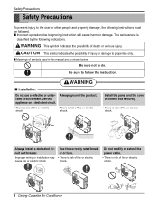
... cause harm or damage. Safety Presautions Safety Precautions To prevent injury to the user or other people and property damage, the following indications. Use this manual are as shown below. This symbol indicates the possibility of fire or electric shock. Be sure not to follow the instruction. Be sure to do...
... cause harm or damage. Safety Presautions Safety Precautions To prevent injury to the user or other people and property damage, the following indications. Use this manual are as shown below. This symbol indicates the possibility of fire or electric shock. Be sure not to follow the instruction. Be sure to do...
Service Manual
Page 5
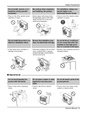
... the product get wet. • There is risk of fire or electric shock. • There is risk of fire, electric shock, explosion, or injury. Service Manual 5 Safety Presautions Do not install, remove, or reinstall the unit by yourself (customer). • There is risk of fire, failure of the product, or electric...
... the product get wet. • There is risk of fire or electric shock. • There is risk of fire, electric shock, explosion, or injury. Service Manual 5 Safety Presautions Do not install, remove, or reinstall the unit by yourself (customer). • There is risk of fire, failure of the product, or electric...

Service Manual
Page 7
.... Do not use harsh detergents, solvents, etc. • There is risk of personal injury and failure of the product when removing the air filter. Service Manual 7 Keep level even when installing the product. • To avoid vibration or water leakage.
.... Do not use harsh detergents, solvents, etc. • There is risk of personal injury and failure of the product when removing the air filter. Service Manual 7 Keep level even when installing the product. • To avoid vibration or water leakage.

Service Manual
Page 9
... of the two temperatures. For example direct drafts can be annoying, leading to discomfort and reduced productivity vane control helps to eliminate this problem. - Service Manual 9 After one is the function for controlling the unit can be done. Air Flow can be controlled easily regarding any of the power, unit will...
... of the two temperatures. For example direct drafts can be annoying, leading to discomfort and reduced productivity vane control helps to eliminate this problem. - Service Manual 9 After one is the function for controlling the unit can be done. Air Flow can be controlled easily regarding any of the power, unit will...

Service Manual
Page 11
Service Manual 11 control Electric heater (Operation) High ceiling operation Hot start Self diagnosis Soft dry operation Auto changeover Auto cleaning Auto operation(Artificial intelligence) Auto restart ...
Service Manual 11 control Electric heater (Operation) High ceiling operation Hot start Self diagnosis Soft dry operation Auto changeover Auto cleaning Auto operation(Artificial intelligence) Auto restart ...

Service Manual
Page 13
... 1 LO SLo Filter Out door 2ndF Time ZONE 1234 Timer Operation unit No Func Program set the current time and clear the setting time. 2. Service Manual 13 Time 01 03 05 07 09 11 13 15 17 19 21 23 3 17 2 10 5 11 12 Timer Cancel 2ndF 6 13 Program Week Holiday...
... 1 LO SLo Filter Out door 2ndF Time ZONE 1234 Timer Operation unit No Func Program set the current time and clear the setting time. 2. Service Manual 13 Time 01 03 05 07 09 11 13 15 17 19 21 23 3 17 2 10 5 11 12 Timer Cancel 2ndF 6 13 Program Week Holiday...

Service Manual
Page 15
... 700 PVE 2100(74.1) R410A EEV 2R * 36C * 20 6 / 370 Direct Drive Side discharge 51(1801) 55 6.35(1/4) 12.7(1/2) 30(100) 15(50) AT-C343HLFO (LCU340CP /LC340CPO) 9.96 34,000 3.6 17 38 2 / 208-230 / 60 3 * 3.3(12) 4 * 2.1(14) 900 * 1160 * 370(357/16 * 4511/16 * 149/16) 86(190) 93(205) 1 ROTARY...(inch) Gas mm(inch) Max. elevation Indoor unit - piping length Main piping m(ft) Max. Conversion Formula kW = Btu/h × 0.0002931 CFM = CMM × 35.3 Service Manual 15 Indoor Temperature 26.7°C(80°F) DB /19.4°C(66.9°F) WB -
... 700 PVE 2100(74.1) R410A EEV 2R * 36C * 20 6 / 370 Direct Drive Side discharge 51(1801) 55 6.35(1/4) 12.7(1/2) 30(100) 15(50) AT-C343HLFO (LCU340CP /LC340CPO) 9.96 34,000 3.6 17 38 2 / 208-230 / 60 3 * 3.3(12) 4 * 2.1(14) 900 * 1160 * 370(357/16 * 4511/16 * 149/16) 86(190) 93(205) 1 ROTARY...(inch) Gas mm(inch) Max. elevation Indoor unit - piping length Main piping m(ft) Max. Conversion Formula kW = Btu/h × 0.0002931 CFM = CMM × 35.3 Service Manual 15 Indoor Temperature 26.7°C(80°F) DB /19.4°C(66.9°F) WB -

Service Manual
Page 19
Wiring Diagrams 1. Indoor Unit LCN240CP/LC240CPI/LCN340CP/LC340CPI Wiring Diagrams Connector Number CN-POWER CN-MOTOR CN-DPUMP CN-DISP CN-FLOAT CN-REMO CN-CC CN-ROOM CN-PIPE1 CN-PIPE2 CN-GRILL CN-PTC CN-HVB Location AC power supply BLDC fan motor output Drain pump output Display Float switch input Remote control Dry-contact Room sensor In-pipe thermistor Out-pipe thermistor Elevation grille PTC Heater HVB Ass'y (Air cleaner) Service Manual 19
Wiring Diagrams 1. Indoor Unit LCN240CP/LC240CPI/LCN340CP/LC340CPI Wiring Diagrams Connector Number CN-POWER CN-MOTOR CN-DPUMP CN-DISP CN-FLOAT CN-REMO CN-CC CN-ROOM CN-PIPE1 CN-PIPE2 CN-GRILL CN-PTC CN-HVB Location AC power supply BLDC fan motor output Drain pump output Display Float switch input Remote control Dry-contact Room sensor In-pipe thermistor Out-pipe thermistor Elevation grille PTC Heater HVB Ass'y (Air cleaner) Service Manual 19

Service Manual
Page 21
Refrigerant Cycle Diagrams 1. Thermistor Capacity 24k 34k Pipe Size(Diameter:Ø) inch Gas Liquid 1/4 1/2 1/4 5/8 Piping length (ft.) Rated Max. 25 100 115 Elevation (ft.) Rated Max. 16 50 16 66 Additional Refrigerant (oz/ft) 0.22 0.32 Service Manual 21 Cooling Only Models INDOOR UNIT OUTDOOR UNIT Refrigerant Cycle Diagrams Capillary Tube H/EX Gas Side Thermistor Accumulator Check Valve High pressure S/W Thermistor Check Valve Thermistor (Air) Heat Exchanger Constant Compressor 1 Constant Compressor 2 GAS SIDE LIQUID SIDE E.E.V.
Refrigerant Cycle Diagrams 1. Thermistor Capacity 24k 34k Pipe Size(Diameter:Ø) inch Gas Liquid 1/4 1/2 1/4 5/8 Piping length (ft.) Rated Max. 25 100 115 Elevation (ft.) Rated Max. 16 50 16 66 Additional Refrigerant (oz/ft) 0.22 0.32 Service Manual 21 Cooling Only Models INDOOR UNIT OUTDOOR UNIT Refrigerant Cycle Diagrams Capillary Tube H/EX Gas Side Thermistor Accumulator Check Valve High pressure S/W Thermistor Check Valve Thermistor (Air) Heat Exchanger Constant Compressor 1 Constant Compressor 2 GAS SIDE LIQUID SIDE E.E.V.

Service Manual
Page 23
... piping hole on the wall, roof or rooftop, anchor the mounting base securely with an anti-vibration rubber. Indoor Wall Outdoor 5~7mm (0.20~0.28inch) Service Manual 23 Indoor Unit Installation 150mm(5.91inch) Hanging bolt (W3/8 or M10) Nut (W3/8 or M10) Spring washer (M10) Keep the length of the bolt from...
... piping hole on the wall, roof or rooftop, anchor the mounting base securely with an anti-vibration rubber. Indoor Wall Outdoor 5~7mm (0.20~0.28inch) Service Manual 23 Indoor Unit Installation 150mm(5.91inch) Hanging bolt (W3/8 or M10) Nut (W3/8 or M10) Spring washer (M10) Keep the length of the bolt from...

Service Manual
Page 25
... from the decoration panel. (Remove the hook for cool air leakage Air conditioner unit Air Cool air leakage (no good) Ceiling board Decoration panel Service Manual 25 Hook the decoration panel key hole ( ) on the unit body. (Tighten by amount 10mm(0.39inch) in step above, and slide the panel so that...
... from the decoration panel. (Remove the hook for cool air leakage Air conditioner unit Air Cool air leakage (no good) Ceiling board Decoration panel Service Manual 25 Hook the decoration panel key hole ( ) on the unit body. (Tighten by amount 10mm(0.39inch) in step above, and slide the panel so that...

Service Manual
Page 29
.... • Proper starting voltage is maintained at more than 8°C(14.4°F). HAND OVER Teach the customer the operation and maintenance procedures, using the operation manual (air filter cleaning, temperature control, etc.). Operate the unit for the air conditioner. Connect the power supply cord to the independent power supply. • Circuit... is as follows: 1) Never fail to the compressor. Ensure the difference between power source and the unit. 3) The screw which the unit is required. 2. Service Manual 29 2) Connection of the intake and discharge air. 2.
.... • Proper starting voltage is maintained at more than 8°C(14.4°F). HAND OVER Teach the customer the operation and maintenance procedures, using the operation manual (air filter cleaning, temperature control, etc.). Operate the unit for the air conditioner. Connect the power supply cord to the independent power supply. • Circuit... is as follows: 1) Never fail to the compressor. Ensure the difference between power source and the unit. 3) The screw which the unit is required. 2. Service Manual 29 2) Connection of the intake and discharge air. 2.

Service Manual
Page 31
... Units by only one Wired Remote Controller, and each units. • Use a wire more than 3.3m(10.8ft) 2.7~3.3m(8.9~10.8ft) less than 0.5mm2 Service Manual 31 Connecting Cable(Local Supply) AUTO SWING OPERATION SET TEMP Room Temp FAN SPEED SUB FUNCTION HI AUTO Heater Preheat MED JET Defrost Humidify LO...
... Units by only one Wired Remote Controller, and each units. • Use a wire more than 3.3m(10.8ft) 2.7~3.3m(8.9~10.8ft) less than 0.5mm2 Service Manual 31 Connecting Cable(Local Supply) AUTO SWING OPERATION SET TEMP Room Temp FAN SPEED SUB FUNCTION HI AUTO Heater Preheat MED JET Defrost Humidify LO...

Service Manual
Page 33
... the voltage of outdoor PCB Ass'y. Troubleshooting Guide Turn off the main power and wait until LED on outdoor PCB is off Turn on Service Manual 33 Check the Auto Addressing Work Confirm Auto Addresssing work method Replace the PCB Ass'y * The product's operation starts at all. Check the connecting state...
... the voltage of outdoor PCB Ass'y. Troubleshooting Guide Turn off the main power and wait until LED on outdoor PCB is off Turn on Service Manual 33 Check the Auto Addressing Work Confirm Auto Addresssing work method Replace the PCB Ass'y * The product's operation starts at all. Check the connecting state...

Service Manual
Page 35
... in relay for indoor temperature is attached as close as to the relay. Check the sensor for COMP Below DC 1V (app) About DC12V Service Manual 35 Check Relay(RY - Check point COMP ON COMP OFF Between two pin of Heat Exchanger(EVA). When the sensor circuit for driving compressor. •...
... in relay for indoor temperature is attached as close as to the relay. Check the sensor for COMP Below DC 1V (app) About DC12V Service Manual 35 Check Relay(RY - Check point COMP ON COMP OFF Between two pin of Heat Exchanger(EVA). When the sensor circuit for driving compressor. •...

Service Manual
Page 37
... that are no problems after above checks • Confirm the assembly conditions that there is DC +12V between pin (RED) of the Vertical Louver Service Manual 37 If there are catching and interfering parts in the rotation radial of CN-U/D and GND.
... that are no problems after above checks • Confirm the assembly conditions that there is DC +12V between pin (RED) of the Vertical Louver Service Manual 37 If there are catching and interfering parts in the rotation radial of CN-U/D and GND.

Service Manual
Page 39
...;/ at 25°C(77°F) (Unplugged) Normal voltage : 2.5Vdc / at 25°C(77°F), then sensor is abnormal. ¡ Repair or Change the PCB. Service Manual 39 Estimate the resistance of the sensor is 10KΩ/ 5KΩ at 25°C(77°F) (plugged) 10kΩ Ω 2.5Vdc V Check the resistance...
...;/ at 25°C(77°F) (Unplugged) Normal voltage : 2.5Vdc / at 25°C(77°F), then sensor is abnormal. ¡ Repair or Change the PCB. Service Manual 39 Estimate the resistance of the sensor is 10KΩ/ 5KΩ at 25°C(77°F) (plugged) 10kΩ Ω 2.5Vdc V Check the resistance...

Service Manual
Page 41
Check the resistance of water 4. Service Manual 41 Check the volt. Check the wire connection. (Open, Soldered poorly) ¡ Repair the connection or change the PCB. 2. Check the level of float switch (...
Check the resistance of water 4. Service Manual 41 Check the volt. Check the wire connection. (Open, Soldered poorly) ¡ Repair the connection or change the PCB. 2. Check the level of float switch (...


