

User Guide
Page 8
... the display operates normally(On Mode). The best display mode is in the On Screen Display. If the display is 17 inch monitor : 1280 x 1024 19 inch monitor : 1280 x 1024 Power Button Use this button to enter a selection in Sleep Mode (Energy Saving), this indicator color changes to amber. Control Panel...
... the display operates normally(On Mode). The best display mode is in the On Screen Display. If the display is 17 inch monitor : 1280 x 1024 19 inch monitor : 1280 x 1024 Power Button Use this button to enter a selection in Sleep Mode (Energy Saving), this indicator color changes to amber. Control Panel...

User Guide
Page 19
...Form Separate TTL, Positive/Negative SOG (Sync On Green) Digital Signal Input Input Form 15 pin D-Sub Connector DVI - Specifications 19 inch Display Sync Input Video Input Resolution Plug&Play Power Consumption Dimensions &Weight Tilt Range Power Input Environmental Conditions Stand Base Signal ...cable Power cord 19 inches (48.19 cm) Flat Panel Active matrix-TFT LCD Anti-Glare coating 19 inches viewable 0.294 mm pixel pitch Horizontal Freq. A18 D connector (Digital) RGB Analog ...
...Form Separate TTL, Positive/Negative SOG (Sync On Green) Digital Signal Input Input Form 15 pin D-Sub Connector DVI - Specifications 19 inch Display Sync Input Video Input Resolution Plug&Play Power Consumption Dimensions &Weight Tilt Range Power Input Environmental Conditions Stand Base Signal ...cable Power cord 19 inches (48.19 cm) Flat Panel Active matrix-TFT LCD Anti-Glare coating 19 inches viewable 0.294 mm pixel pitch Horizontal Freq. A18 D connector (Digital) RGB Analog ...
User Guide
Page 21
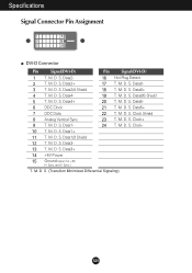
... T. Data5- 6 DDC Clock 21 T. Clock Shield 8 Analog Vertical Sync. 23 T. M. M. S. M. Data1- 24 T. S. Data0/5 Shield 5 T. M. M. S. (Transition Minimized Differential Signaling) A20 M. S. D. M. S. D. D. M. Data3- 13 T. Data2+ 17 T. Sync. Data4- 19 T. M. D. M. Specifications Signal Connector Pin Assignment 1 8 9 16 17 24 DVI-D Connector Pin Signal(DVI-D) Pin Signal(DVI-D) 1 T. S. S. Clock+ 9 T. Data1/3 Shield 12 T.
... T. Data5- 6 DDC Clock 21 T. Clock Shield 8 Analog Vertical Sync. 23 T. M. M. S. M. Data1- 24 T. S. Data0/5 Shield 5 T. M. M. S. (Transition Minimized Differential Signaling) A20 M. S. D. M. S. D. D. M. Data3- 13 T. Data2+ 17 T. Sync. Data4- 19 T. M. D. M. Specifications Signal Connector Pin Assignment 1 8 9 16 17 24 DVI-D Connector Pin Signal(DVI-D) Pin Signal(DVI-D) 1 T. S. S. Clock+ 9 T. Data1/3 Shield 12 T.