
Owner's Manual
Page 4
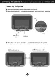
Place the monitor with its front facing downward on a soft cloth. 2. L194WTM, L204WTM Connecting the speaker 1. After setting up the speaker, connect the Audio DC-In Cable to the back of the product. Slot Audio DC-In Cable Hook 3. Insert the protruding hook of the speaker in the direction of the slot in the back of the product. 19 inch monitor 20.1 inch monitor A3 Connecting the speakers - The feature is only for speaker models -
Place the monitor with its front facing downward on a soft cloth. 2. L194WTM, L204WTM Connecting the speaker 1. After setting up the speaker, connect the Audio DC-In Cable to the back of the product. Slot Audio DC-In Cable Hook 3. Insert the protruding hook of the speaker in the direction of the slot in the back of the product. 19 inch monitor 20.1 inch monitor A3 Connecting the speakers - The feature is only for speaker models -
Owner's Manual
Page 5
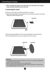
...Stand Base(Front, Rear) into the product in the correct direction as shown in the picture. Place the monitor with its front facing downward on a soft cloth. 2. Once assembled take the monitor up the monitor, ensure that the power to disconnect it "click". 3. REAR REAR Connecting the Display Before setting up ... the general model of connection. Connecting the stand 1. Make sure you push it until you connect the stand base, try not to the monitor, the computer system, and other attached devices is turned off. The product may differ from the items shown in the picture.
...Stand Base(Front, Rear) into the product in the correct direction as shown in the picture. Place the monitor with its front facing downward on a soft cloth. 2. Once assembled take the monitor up the monitor, ensure that the power to disconnect it "click". 3. REAR REAR Connecting the Display Before setting up ... the general model of connection. Connecting the stand 1. Make sure you push it until you connect the stand base, try not to the monitor, the computer system, and other attached devices is turned off. The product may differ from the items shown in the picture.
Owner's Manual
Page 6
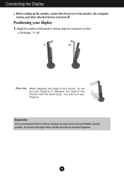
... an ergonomic and comfortable viewing position, the forward tilt angle of the monitor should not exceed 5 degrees. You can hurt your display 1. Connecting the Display Before setting up the monitor, ensure that in between the head of the monitor and the stand body. Tilt Range : -5˚~20˚ 20 Warning...: When adjusting the angle of the panel in various ways for maximum comfort. A5 Adjust the position of the screen, do not put your finger(s) in order to the monitor, the computer system...
... an ergonomic and comfortable viewing position, the forward tilt angle of the monitor should not exceed 5 degrees. You can hurt your display 1. Connecting the Display Before setting up the monitor, ensure that in between the head of the monitor and the stand body. Tilt Range : -5˚~20˚ 20 Warning...: When adjusting the angle of the panel in various ways for maximum comfort. A5 Adjust the position of the screen, do not put your finger(s) in order to the monitor, the computer system...
Owner's Manual
Page 7
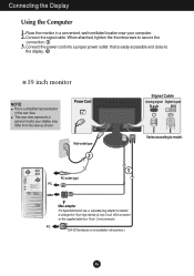
Connect the power cord into a proper power outlet that is a simplified representation of the rear view. Place the monitor in all countries.) Signal Cable Analog signal Digital signal D-sub DVI Varies according to a 15 pin 2 row connector. your computer. 2. This ... general model; A6 Connecting the Display Using the Computer 1. Connect the signal cable. When attached, tighten the thumbscrews to the display. 2 19 inch monitor NOTE This is easily accessible and close to secure the connection. 1 3. Power Cord Wall-outlet type 2 1 PC-outlet type PC MAC Mac adapter ...
Connect the power cord into a proper power outlet that is a simplified representation of the rear view. Place the monitor in all countries.) Signal Cable Analog signal Digital signal D-sub DVI Varies according to a 15 pin 2 row connector. your computer. 2. This ... general model; A6 Connecting the Display Using the Computer 1. Connect the signal cable. When attached, tighten the thumbscrews to the display. 2 19 inch monitor NOTE This is easily accessible and close to secure the connection. 1 3. Power Cord Wall-outlet type 2 1 PC-outlet type PC MAC Mac adapter ...
Owner's Manual
Page 8
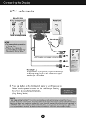
... adapter For Apple Macintosh use, a separate plug adapter is executed automatically. (Only Analog Mode) NOTE ' Self Image Setting Function'? A7 When monitor power is turned on, the 'Self Image Setting Function' is needed to change the 15 pin high density (3 row) D-sub VGA connector ... display to turn the power on the OSD adjustment menu. This function provides the user with optimal display settings.When the user connects the monitor for individual input signals. Otherwise, you want to model. This rear view represents a general model; your display may execute the ' Factory...
... adapter For Apple Macintosh use, a separate plug adapter is executed automatically. (Only Analog Mode) NOTE ' Self Image Setting Function'? A7 When monitor power is turned on, the 'Self Image Setting Function' is needed to change the 15 pin high density (3 row) D-sub VGA connector ... display to turn the power on the OSD adjustment menu. This function provides the user with optimal display settings.When the user connects the monitor for individual input signals. Otherwise, you want to model. This rear view represents a general model; your display may execute the ' Factory...
Owner's Manual
Page 11
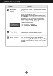
... Screen Display(OSD). Power Indicator This Indicator lights up blue when the display operates normally(On Mode). If the display is 19 inch monitor : 1440 x 900 20.1 inch monitor : 1680 x 1050 Power Button Use this button to turn the display on or off. A10 Control Panel Functions Control AUTO/SET Button Function...
... Screen Display(OSD). Power Indicator This Indicator lights up blue when the display operates normally(On Mode). If the display is 19 inch monitor : 1440 x 900 20.1 inch monitor : 1680 x 1050 Power Button Use this button to turn the display on or off. A10 Control Panel Functions Control AUTO/SET Button Function...
Owner's Manual
Page 14
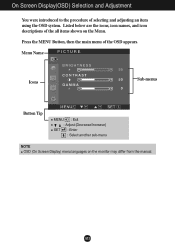
A13 Menu Name PICTURE Icons Sub-menus Button Tip MENU : Exit : Adjust (Decrease/Increase) SET : Enter : Select another sub-menu NOTE OSD (On Screen Display) menu languages on the Menu. Listed below are the icons, icon names, and icon descriptions of selecting and adjusting an item using the OSD system. On Screen Display(OSD) Selection and Adjustment You were introduced to the procedure of the all items shown on the monitor may differ from the manual. Press the MENU Button, then the main menu of the OSD appears.
A13 Menu Name PICTURE Icons Sub-menus Button Tip MENU : Exit : Adjust (Decrease/Increase) SET : Enter : Select another sub-menu NOTE OSD (On Screen Display) menu languages on the Menu. Listed below are the icons, icon names, and icon descriptions of selecting and adjusting an item using the OSD system. On Screen Display(OSD) Selection and Adjustment You were introduced to the procedure of the all items shown on the monitor may differ from the manual. Press the MENU Button, then the main menu of the OSD appears.
Owner's Manual
Page 15
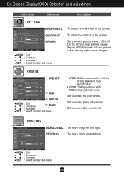
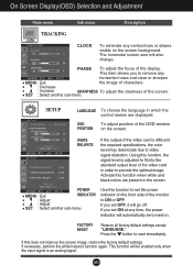
POSITION POSITION HORIZONTAL To move image up and down. VERTICAL To move image left and right. Set your own gamma value. : -50/0/50 On the monitor, high gamma values display whitish images and low gamma values display high contrast images. To adjust the contrast of the screen. Set your own green ...
POSITION POSITION HORIZONTAL To move image up and down. VERTICAL To move image left and right. Set your own gamma value. : -50/0/50 On the monitor, high gamma values display whitish images and low gamma values display high contrast images. To adjust the contrast of the screen. Set your own green ...
Owner's Manual
Page 16
... time, the power indicator will be turned on the screen. If necessary, perform the white balance function again. PHASE To adjust the focus of the monitor to remove any vertical bars or stripes visible on the front side of the display. If you to ON or OFF. A15 Using this function...
... time, the power indicator will be turned on the screen. If necessary, perform the white balance function again. PHASE To adjust the focus of the monitor to remove any vertical bars or stripes visible on the front side of the display. If you to ON or OFF. A15 Using this function...
Owner's Manual
Page 17
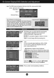
... when not applied Main menu Sub menu Description MOVIE This feature lets you execute F-ENGINE, two tones will appear on the right side of the monitor. A16 NORMAL This is under normal operating conditions. The applied screen will appear on the left side, whereas the non-applied screen will appear on...
... when not applied Main menu Sub menu Description MOVIE This feature lets you execute F-ENGINE, two tones will appear on the right side of the monitor. A16 NORMAL This is under normal operating conditions. The applied screen will appear on the left side, whereas the non-applied screen will appear on...
Owner's Manual
Page 20
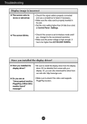
... can also download the driver from the display driver CD (or diskette) that comes with your display. Settings. Have you see an "Unrecognized monitor, Plug&Play (VESA DDC) monitor found" message? • Make sure to check if the video card supports Plug&Play function. Or, you installed the display driver? • Be...
... can also download the driver from the display driver CD (or diskette) that comes with your display. Settings. Have you see an "Unrecognized monitor, Plug&Play (VESA DDC) monitor found" message? • Make sure to check if the video card supports Plug&Play function. Or, you installed the display driver? • Be...

Owner's Manual
Page 25
... 9 1024 x 768 10 1152 x 870 11 1152 x 900 12 1280 x 1024 13 1280 x 1024 14 1440 x 900 *15 1440 x 900 **16 1440 x 900 20.1 inch monitor Display Modes (Resolution) 1 720 x 400 2 640 x 480 3 640 x 480 4 800 x 600 5 800 x 600 6 1024 x 768 7 1024 x 768 8 1152 x 864 9 1280 x 1024 10 1280 x 1024 *11...
... 9 1024 x 768 10 1152 x 870 11 1152 x 900 12 1280 x 1024 13 1280 x 1024 14 1440 x 900 *15 1440 x 900 **16 1440 x 900 20.1 inch monitor Display Modes (Resolution) 1 720 x 400 2 640 x 480 3 640 x 480 4 800 x 600 5 800 x 600 6 1024 x 768 7 1024 x 768 8 1152 x 864 9 1280 x 1024 10 1280 x 1024 *11...

Owner's Manual
Page 27
Wall mount plate(Separate purchase) This is stand-type or will mount type and is purchased. Place the monitor with Wall mount plate. Please refer to the right. 3. Pull the stand to the direction as shown in the image 2 to a locking cable that can ... Slot Connected to separate. 1 2 REAR REAR REAR FRONT REAR FRONT REAR FRONT REAR FRONT .4 Install the Wall mount plate. Installing the Wall mount plate This monitor satisfies the specifications of the stand as shown in the image 1 and bend slightly to the installation guide for more details, which is provided when...
Wall mount plate(Separate purchase) This is stand-type or will mount type and is purchased. Place the monitor with Wall mount plate. Please refer to the right. 3. Pull the stand to the direction as shown in the image 2 to a locking cable that can ... Slot Connected to separate. 1 2 REAR REAR REAR FRONT REAR FRONT REAR FRONT REAR FRONT .4 Install the Wall mount plate. Installing the Wall mount plate This monitor satisfies the specifications of the stand as shown in the image 1 and bend slightly to the installation guide for more details, which is provided when...


