
Owner's Manual (English)
Page 2
... designed for a replacement. Overloaded AC outlets and extension cords are not sure what type of power supply you are dangerous. They may result in the specifications of time. The power supply cord is certified by the applicable national standards if not being provided by the manufacturer. So are frayed power cords...
... designed for a replacement. Overloaded AC outlets and extension cords are not sure what type of power supply you are dangerous. They may result in the specifications of time. The power supply cord is certified by the applicable national standards if not being provided by the manufacturer. So are frayed power cords...
Owner's Manual (English)
Page 14
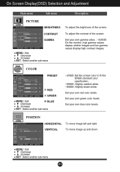
... PICTURE BRIGHTNESS CONTRAST GAMMA MENU : Exit : Decrease : Increase SET : Select another sub-menu • sRGB: Set the screen color to fit the SRGB standard color specification. • 6500K: Slightly reddish white. • 9300K: Slightly bluish white. Set your own blue color levels. MENU : Exit : Decrease : Increase SET : Select another sub-menu...
... PICTURE BRIGHTNESS CONTRAST GAMMA MENU : Exit : Decrease : Increase SET : Select another sub-menu • sRGB: Set the screen color to fit the SRGB standard color specification. • 6500K: Slightly reddish white. • 9300K: Slightly bluish white. Set your own blue color levels. MENU : Exit : Decrease : Increase SET : Select another sub-menu...
Owner's Manual (English)
Page 15
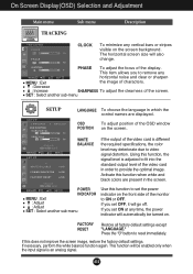
... time, the power indicator will go off. If you set OFF, it will automatically be enabled only when the input signal is different the required specifications, the color level may deteriorate due to remove any horizontal noise and clear or sharpen MENU : Exit the image of characters. : Decrease : Increase SHARPNESS To...
... time, the power indicator will go off. If you set OFF, it will automatically be enabled only when the input signal is different the required specifications, the color level may deteriorate due to remove any horizontal noise and clear or sharpen MENU : Exit the image of characters. : Decrease : Increase SHARPNESS To...
Owner's Manual (English)
Page 17
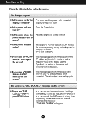
...? A16 G Is the power indicator amber? • If the display is out of this manual and configure your display is connected display connected? See the 'Specifications' section of horizontal or vertical the screen? G Do you see a "CHECK SIGNAL CABLE" message on the PC. G Do you see "OSD LOCKED" when you see...
...? A16 G Is the power indicator amber? • If the display is out of this manual and configure your display is connected display connected? See the 'Specifications' section of horizontal or vertical the screen? G Do you see a "CHECK SIGNAL CABLE" message on the PC. G Do you see "OSD LOCKED" when you see...
Owner's Manual (English)
Page 20
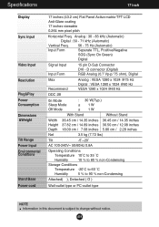
... Freq. 56 - 75 Hz (Automatic) Input Form Separate TTL, Positive/Negative SOG (Sync On Green) Digital Signal Input Input Form 15 pin D-Sub Connector DVI - Specifications 17 inch Display Sync Input Video Input Resolution Plug&Play Power Consumption Dimensions &Weight Tilt Range Power Input Environmental Conditions Stand Base Power cord 17...
... Freq. 56 - 75 Hz (Automatic) Input Form Separate TTL, Positive/Negative SOG (Sync On Green) Digital Signal Input Input Form 15 pin D-Sub Connector DVI - Specifications 17 inch Display Sync Input Video Input Resolution Plug&Play Power Consumption Dimensions &Weight Tilt Range Power Input Environmental Conditions Stand Base Power cord 17...
Owner's Manual (English)
Page 21
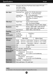
... Freq. 56 - 75 Hz (Automatic) Input Form Separate TTL, Positive/Negative SOG (Sync On Green) Digital Signal Input Input Form 15 pin D-Sub Connector DVI - Specifications 19 inch Display Sync Input Video Input Resolution Plug&Play Power Consumption Dimensions &Weight Tilt Range Power Input Environmental Conditions Stand Base Power cord 19...
... Freq. 56 - 75 Hz (Automatic) Input Form Separate TTL, Positive/Negative SOG (Sync On Green) Digital Signal Input Input Form 15 pin D-Sub Connector DVI - Specifications 19 inch Display Sync Input Video Input Resolution Plug&Play Power Consumption Dimensions &Weight Tilt Range Power Input Environmental Conditions Stand Base Power cord 19...
Owner's Manual (English)
Page 22
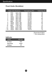
Specifications Preset Modes (Resolution) Display Modes (Resolution) 1 VGA 640 x 350 2 VGA 720 x 400 3 VGA 640 x 480 4 VESA 640 x 480 5 VESA 800 x 600 6 VESA 800 x 600 7 MAC 832 x 624 8 VESA 1024 x 768 9 VESA 1024 x 768 10 MAC 1152 x 870 11 VESA 1152 x 900 *12 VESA 1280 x 1024 **13 VESA 1280 x 1024 Horizontal Freq. (kHz) 31.469 31.468 31.469 37.500 37.879 46.875 49.725 48.363 60.023 68.681 61.805 63.981 79.976 Vertical Freq. (Hz) 70 70 60 75 60 75 75 60 75 75 65 60 75 * Recommend Mode ** Only Analog Mode Indicator MODE On Mode Sleep Mode Off Mode LED Color blue amber Off A21
Specifications Preset Modes (Resolution) Display Modes (Resolution) 1 VGA 640 x 350 2 VGA 720 x 400 3 VGA 640 x 480 4 VESA 640 x 480 5 VESA 800 x 600 6 VESA 800 x 600 7 MAC 832 x 624 8 VESA 1024 x 768 9 VESA 1024 x 768 10 MAC 1152 x 870 11 VESA 1152 x 900 *12 VESA 1280 x 1024 **13 VESA 1280 x 1024 Horizontal Freq. (kHz) 31.469 31.468 31.469 37.500 37.879 46.875 49.725 48.363 60.023 68.681 61.805 63.981 79.976 Vertical Freq. (Hz) 70 70 60 75 60 75 75 60 75 75 65 60 75 * Recommend Mode ** Only Analog Mode Indicator MODE On Mode Sleep Mode Off Mode LED Color blue amber Off A21
Owner's Manual (English)
Page 23
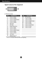
Data2- 16 Hot Plug Detect 2 T. Data2+ 17 T. D. M. D. Data5+ 7 DDC Data 22 T. Data1- 24 T. D. D. Specifications Signal Connector Pin Assignment 1 8 9 16 17 24 DVI-D Connector Pin Signal(DVI-D) Pin Signal(DVI-D) 1 T. M. M. D. S. M. D. Data0/5 Shield 5 T. M. S. Data4+ 20 T. M. S. S. S. Data1+ 11 T. Data1/3 Shield 12 T. M. Data3- ...
Data2- 16 Hot Plug Detect 2 T. Data2+ 17 T. D. M. D. Data5+ 7 DDC Data 22 T. Data1- 24 T. D. D. Specifications Signal Connector Pin Assignment 1 8 9 16 17 24 DVI-D Connector Pin Signal(DVI-D) Pin Signal(DVI-D) 1 T. M. M. D. S. M. D. Data0/5 Shield 5 T. M. S. Data4+ 20 T. M. S. S. S. Data1+ 11 T. Data1/3 Shield 12 T. M. Data3- ...
Owner's Manual (English)
Page 24
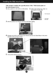
Put a cushion or soft cloth on the cushion or soft cloth. Place the monitor face down on a flat surface. The Head part 3. A23 Hold the product as it follows and lift up the Stand slightly. Change your hold on the product as it follows and turn the Stand Base in the arrow direction until you hear a "click." 5. Installing the Wall mount plate This monitor satisfies the specifications of the Wall mount plate or the interchange device. 1. 2. The Stand base part 4. Pull out the Stand to remove.
Put a cushion or soft cloth on the cushion or soft cloth. Place the monitor face down on a flat surface. The Head part 3. A23 Hold the product as it follows and lift up the Stand slightly. Change your hold on the product as it follows and turn the Stand Base in the arrow direction until you hear a "click." 5. Installing the Wall mount plate This monitor satisfies the specifications of the Wall mount plate or the interchange device. 1. 2. The Stand base part 4. Pull out the Stand to remove.
