
Service Manual
Page 1
website http://www.lgservice.com LG LG Room Air Conditioner SERVICE MANUAL MODELS: LW1800PR LW1800ER LW1800ERZ3 LW1500PR LW1500PRY3 LWP1830WAL LWP1820PDL LWP1820PEL LWC182PLMM0 LWC183PLMD1 LWC212PLMM0 LW1804ER LW1800PRZ3 HBLG1803R CAUTION • BEFORE SERVICING THE UNIT, READ THE SAFETY PRECAUTIONS IN THIS MANUAL. • ONLY FOR AUTHORIZED SERVICE PERSONNEL.
website http://www.lgservice.com LG LG Room Air Conditioner SERVICE MANUAL MODELS: LW1800PR LW1800ER LW1800ERZ3 LW1500PR LW1500PRY3 LWP1830WAL LWP1820PDL LWP1820PEL LWC182PLMM0 LWC183PLMD1 LWC212PLMM0 LW1804ER LW1800PRZ3 HBLG1803R CAUTION • BEFORE SERVICING THE UNIT, READ THE SAFETY PRECAUTIONS IN THIS MANUAL. • ONLY FOR AUTHORIZED SERVICE PERSONNEL.

Service Manual
Page 2
Air Conditioner Service Manual TABLE OF CONTENTS Safety Precautions...3 Dimensions ...5 Outside dimensions...5 Product Specifications ...6 Installation ...7 Select the Best Location ...7 Installation Check ...7 How to Secure the Drain Pipe ...7 How to ...
Air Conditioner Service Manual TABLE OF CONTENTS Safety Precautions...3 Dimensions ...5 Outside dimensions...5 Product Specifications ...6 Installation ...7 Select the Best Location ...7 Installation Check ...7 How to Secure the Drain Pipe ...7 How to ...

Service Manual
Page 3
WARNING This symbol indicates the possibility of symbols used in this manual are as shown below. s Meanings of death or serious injury. s Installation WARNING Do not use the power plug and socket with the ground terminal. • ... of electric shock. s Incorrect operation due to do. Be sure not to ignoring instruction will cause harm or damage. Be sure to properties only. Service Manual 3 Always use damaged power cord plugs, or a loose socket.
WARNING This symbol indicates the possibility of symbols used in this manual are as shown below. s Meanings of death or serious injury. s Installation WARNING Do not use the power plug and socket with the ground terminal. • ... of electric shock. s Incorrect operation due to do. Be sure not to ignoring instruction will cause harm or damage. Be sure to properties only. Service Manual 3 Always use damaged power cord plugs, or a loose socket.

Service Manual
Page 5
Dimensions Outside Dimensions D W Cool Energy Saver F1 LOW 'F F2 MED F3 HIGH Fan Dry Timer TEMP MODE TIMER FAN SPEED POWER H Dimension W H D Model mm(inch) mm(inch) mm(inch) ALL MODELS 660(25 31/32) 428(16 27/32) 680(26 27/32) Service Manual 5 NOTICE This symbol indicates special notes. This symbol alerts you to the air conditioner. Dimensions Symbols Used in this Manual This symbol alerts you to hazards that could cause harm to the risk of electric shock.
Dimensions Outside Dimensions D W Cool Energy Saver F1 LOW 'F F2 MED F3 HIGH Fan Dry Timer TEMP MODE TIMER FAN SPEED POWER H Dimension W H D Model mm(inch) mm(inch) mm(inch) ALL MODELS 660(25 31/32) 428(16 27/32) 680(26 27/32) Service Manual 5 NOTICE This symbol indicates special notes. This symbol alerts you to the air conditioner. Dimensions Symbols Used in this Manual This symbol alerts you to hazards that could cause harm to the risk of electric shock.
Service Manual
Page 7
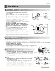
... in the power cord. Install the drain pan over the corner of the unit) to fit drain pan to drain (consult a dealer). Fig. 1 Fig. 2 2. Service Manual 7 Install the unit a little obliquely outward not to leak the condensed water into the hole by considering the hole of the cabinet where you need...
... in the power cord. Install the drain pan over the corner of the unit) to fit drain pan to drain (consult a dealer). Fig. 1 Fig. 2 2. Service Manual 7 Install the unit a little obliquely outward not to leak the condensed water into the hole by considering the hole of the cabinet where you need...

Service Manual
Page 9
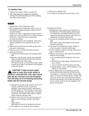
... Top retainer bar and Frame guides. Foam-Seal Figure 4 8. Top retainer bar Top retainer bar Foam-PE Screw (Type A) Frame guide Figure 5 Screw (Type A) Service Manual 9 Slide the unit out from Foam-PE with 10 screws (Type A) at both sides for later use. 2. Suggested tool Requirements SCREWDRIVER(+, -), RULER, KNIFE, HAMMER, PENCIL...
... Top retainer bar and Frame guides. Foam-Seal Figure 4 8. Top retainer bar Top retainer bar Foam-PE Screw (Type A) Frame guide Figure 5 Screw (Type A) Service Manual 9 Slide the unit out from Foam-PE with 10 screws (Type A) at both sides for later use. 2. Suggested tool Requirements SCREWDRIVER(+, -), RULER, KNIFE, HAMMER, PENCIL...

Service Manual
Page 11
... Screw Figure 11 Figure 12 9. Figure 14 Installation Screw(Type C) Power Cord Screw (Type A) Foam-Strip Window locking bracket TEMP TIME SPFAENED MODE POWER Service Manual 11 Lift the inlet grille and secure it with a screw (Type C). (See Fig. 13) Figure 13 10. Window installation of the cabinet. Slide the unit...
... Screw Figure 11 Figure 12 9. Figure 14 Installation Screw(Type C) Power Cord Screw (Type A) Foam-Strip Window locking bracket TEMP TIME SPFAENED MODE POWER Service Manual 11 Lift the inlet grille and secure it with a screw (Type C). (See Fig. 13) Figure 13 10. Window installation of the cabinet. Slide the unit...

Service Manual
Page 13
You can select the fan speed in three steps high, low or medium. Service Manual 13 Starting operation (1Hour ➔ 2Hours ➔ 3Hours ➔ 4Hours ➔ 5Hours ➔ 6Hours ➔ 7Hours ➔ 8Hours ➔ 9Hours ➔ 10Hours ➔ 11Hours ➔ ...
You can select the fan speed in three steps high, low or medium. Service Manual 13 Starting operation (1Hour ➔ 2Hours ➔ 3Hours ➔ 4Hours ➔ 5Hours ➔ 6Hours ➔ 7Hours ➔ 8Hours ➔ 9Hours ➔ 10Hours ➔ 11Hours ➔ ...
Service Manual
Page 15
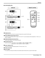
... is set by 1 hour. 6 SIGNAL RECEIVER 7 AUTO SWING The vertical louver swings horizontally by 2˚C 1 hour later. FAN SPEED SELECTOR Select the fan speed. Service Manual 15 ROOM TEMPERATURE SETTING BUTTON Control the room temperature within a range of starting and stopping operation. The timer is pressed and stops when you press...
... is set by 1 hour. 6 SIGNAL RECEIVER 7 AUTO SWING The vertical louver swings horizontally by 2˚C 1 hour later. FAN SPEED SELECTOR Select the fan speed. Service Manual 15 ROOM TEMPERATURE SETTING BUTTON Control the room temperature within a range of starting and stopping operation. The timer is pressed and stops when you press...

Service Manual
Page 16
... 16) 4. Remove the front grille. (Refer to section 2) 3. Remove the cabinet. (Refer to section 1) 2. Remove the housing that connects PCB and motor wire in this manual and on the control box.) TEMP MODE Cool COOL FAN En DRY Saevrgery INDOOR FAN HEAT DEFROST DFrayn Timer DESIRED FPFRFE32U1SENAHMRALSAIEUGOEYVTIRTDWRHFAEOGIRREYTR TIMER SPFAENED ˚C POWER...
... 16) 4. Remove the front grille. (Refer to section 2) 3. Remove the cabinet. (Refer to section 1) 2. Remove the housing that connects PCB and motor wire in this manual and on the control box.) TEMP MODE Cool COOL FAN En DRY Saevrgery INDOOR FAN HEAT DEFROST DFrayn Timer DESIRED FPFRFE32U1SENAHMRALSAIEUGOEYVTIRTDWRHFAEOGIRREYTR TIMER SPFAENED ˚C POWER...

Service Manual
Page 17
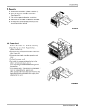
... pan.(Move the air giude lower carefully.) 15. Remove the 5 screws that secures the fan. 6. Disassembly Figure 18 Figure 19 Figure 20 Figure 21 Service Manual 17 Air Guide and Turbo Fan 1. Remove the 2 screws that fasten the evaporator. 9. Pull out the hook of orifice by pushing the tabs and remove...
... pan.(Move the air giude lower carefully.) 15. Remove the 5 screws that secures the fan. 6. Disassembly Figure 18 Figure 19 Figure 20 Figure 21 Service Manual 17 Air Guide and Turbo Fan 1. Remove the 2 screws that fasten the evaporator. 9. Pull out the hook of orifice by pushing the tabs and remove...
Service Manual
Page 19
... at the unit.) TEMP MODE CoolCOOL FAN Ene DRY SFavrgery INDOOR FAN HEAT DEFROST Drayn Timer DESIRED PRFEFUFS3EN2A1RASHAEMULYVITIRGOETRFAEDOWHGIRREYTR TIMER SPFAENED ˚C POWER Figure 26 Service Manual 19 Capacitor 1. Power Cord 1. TEMP MODE CoolCOOL FAN Ene DRY SFavrgery INDOOR FAN HEAT DEFROST Drayn Timer DESIRED PRFEFFUS3E2NA1RAHSAMEULYVITIGOERTRFAEDWHOGIRREYTR TIMER SPFAENED ˚C POWER Disassembly Figure...
... at the unit.) TEMP MODE CoolCOOL FAN Ene DRY SFavrgery INDOOR FAN HEAT DEFROST Drayn Timer DESIRED PRFEFUFS3EN2A1RASHAEMULYVITIRGOETRFAEDOWHGIRREYTR TIMER SPFAENED ˚C POWER Figure 26 Service Manual 19 Capacitor 1. Power Cord 1. TEMP MODE CoolCOOL FAN Ene DRY SFavrgery INDOOR FAN HEAT DEFROST Drayn Timer DESIRED PRFEFFUS3E2NA1RAHSAMEULYVITIGOERTRFAEDWHOGIRREYTR TIMER SPFAENED ˚C POWER Disassembly Figure...
Service Manual
Page 21
... lbs. Braze service valves into the vacuum pump. 3) Operate the vacuum pump vaccum for a few minutes. Repeat steps b. until 600 microns of the charge. Service Manual 21 Replacement of the charge is in the suction line through valves A and B up to valve C by referring to the pinch-off tool with two...
... lbs. Braze service valves into the vacuum pump. 3) Operate the vacuum pump vaccum for a few minutes. Repeat steps b. until 600 microns of the charge. Service Manual 21 Replacement of the charge is in the suction line through valves A and B up to valve C by referring to the pinch-off tool with two...
Service Manual
Page 25
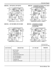
...COMPRESSOR 4 OVERLOAD PROTECTOR 5 DC PCB ASSEMBLY 6 AC PCB ASSEMBLY 7 THERMISTOR 8 PLASMA FILTER ASSY Schematic Diagram s MODEL : LW1800ERZ3/LW1800PR, HBLG1803R LW1800ER/LWP1830WAL 1 BK CN-MOTOR GN/YL BL (GN) MOTOR RD YL OR CN-AC/DC CN-AC/DC 5 DC PCB ASSEMBLY...: LW1500PRY3/LW1500PR LW1800PRZ3/LW1804ER LWC182PLMD1 1 5 7 2 6 3 4 8 Q'TY PER SET 1 1 1 1 1 1 1 1 S: Service Parts N: Non Service Parts REMARKS S S S S S S S S Service Manual 25 s MODEL : LWP1820PDL/LWP1820PEL 1 BK CN-MOTOR CN-AC/DC CN-AC/DC GN/YL BL (GN) MOTOR RD YL DC PCB ASSEMBLY 5 CN-TH1...
...COMPRESSOR 4 OVERLOAD PROTECTOR 5 DC PCB ASSEMBLY 6 AC PCB ASSEMBLY 7 THERMISTOR 8 PLASMA FILTER ASSY Schematic Diagram s MODEL : LW1800ERZ3/LW1800PR, HBLG1803R LW1800ER/LWP1830WAL 1 BK CN-MOTOR GN/YL BL (GN) MOTOR RD YL OR CN-AC/DC CN-AC/DC 5 DC PCB ASSEMBLY...: LW1500PRY3/LW1500PR LW1800PRZ3/LW1804ER LWC182PLMD1 1 5 7 2 6 3 4 8 Q'TY PER SET 1 1 1 1 1 1 1 1 S: Service Parts N: Non Service Parts REMARKS S S S S S S S S Service Manual 25 s MODEL : LWP1820PDL/LWP1820PEL 1 BK CN-MOTOR CN-AC/DC CN-AC/DC GN/YL BL (GN) MOTOR RD YL DC PCB ASSEMBLY 5 CN-TH1...

Service Manual
Page 29
Check gas leakage. Adjusting of air filter. Dirty indoor coil (Heat exchanger) Malfunction of fan Clogged of refrigerant charged. Clean condenser. Malfunction of compressor. Service Manual 29 Check inside gas pressure. Satisfactory operation with temperature difference of inlet & outlet air ; 44~50°F(7~10°C) Replacement of compressor. Repair gas leak. ...
Check gas leakage. Adjusting of air filter. Dirty indoor coil (Heat exchanger) Malfunction of fan Clogged of refrigerant charged. Clean condenser. Malfunction of compressor. Service Manual 29 Check inside gas pressure. Satisfactory operation with temperature difference of inlet & outlet air ; 44~50°F(7~10°C) Replacement of compressor. Repair gas leak. ...

Service Manual
Page 31
... wiring diagram. YES • Replace the Trans. Is output Voltage of Micom is 5V.) YES Is the connection between NO AC and DC OK? Service Manual 31 YES Is the Trans output power NO about AC 14V? YES Is shorted the Trans. NO (The No.14 of IC02D NO DC 5V...
... wiring diagram. YES • Replace the Trans. Is output Voltage of Micom is 5V.) YES Is the connection between NO AC and DC OK? Service Manual 31 YES Is the Trans output power NO about AC 14V? YES Is shorted the Trans. NO (The No.14 of IC02D NO DC 5V...

Service Manual
Page 33
...-Hi or RY-Med or RY-Lo. • Check the wiring diagram. Troubleshooting Guide • Replace IC01M. • Replace IC01M. YES • Reference to OWNER'S MANUAL. • Set the mode key to Energy Saver mode. • Check the Energy Saver mode key. • Check the pattern of IC01M 0V? Possible Trouble... the voltage No.3 of NO CN-AC/DC of Energy Saver does not operate. Possible Trouble 5 The function of AC PCB Ass'y DC 5V? Service Manual 33 Is the voltage NO.1 or 2 or 4 NO of IC01M DC 12V? Is the mode NO key pushed once more from cool mode?
...-Hi or RY-Med or RY-Lo. • Check the wiring diagram. Troubleshooting Guide • Replace IC01M. • Replace IC01M. YES • Reference to OWNER'S MANUAL. • Set the mode key to Energy Saver mode. • Check the Energy Saver mode key. • Check the pattern of IC01M 0V? Possible Trouble... the voltage No.3 of NO CN-AC/DC of Energy Saver does not operate. Possible Trouble 5 The function of AC PCB Ass'y DC 5V? Service Manual 33 Is the voltage NO.1 or 2 or 4 NO of IC01M DC 12V? Is the mode NO key pushed once more from cool mode?

Service Manual
Page 35
... the Trans. YES • Replace D02D~D05D. • Replace IC01D. YES Replace AC PCB Ass'y. • Check the PCB pattern. YES • Replace IC02D. Service Manual 35 NO (208/230V for LWL1230WAL) • Check the Fuse. • Check the wiring diagram. Is output Voltage of IC02D NO DC 5V? NO Is...
... the Trans. YES • Replace D02D~D05D. • Replace IC01D. YES Replace AC PCB Ass'y. • Check the PCB pattern. YES • Replace IC02D. Service Manual 35 NO (208/230V for LWL1230WAL) • Check the Fuse. • Check the wiring diagram. Is output Voltage of IC02D NO DC 5V? NO Is...

Service Manual
Page 37
... or RY-Med or RY-Lo. • Check the wiring diagram. YES Is the voltage No.10 NO of NO CN-AC/DC OK? Service Manual 37 Possible Trouble 5 Remote controller does not operate. YES Is the connection of CN-AC/DC on AC PCB Ass'y DC 5V? YES • Replace...
... or RY-Med or RY-Lo. • Check the wiring diagram. YES Is the voltage No.10 NO of NO CN-AC/DC OK? Service Manual 37 Possible Trouble 5 Remote controller does not operate. YES Is the connection of CN-AC/DC on AC PCB Ass'y DC 5V? YES • Replace...

Service Manual
Page 39
... any change , replace the motor. Check the wire connections, if loose, repair or replace the terminal. If wires are off, refer to low speed. Service Manual 39 Fan motor runs intermittently Fan motor noise. Fan Turbo Loose clamper Worn bearings Voltage Wiring REMEDY Check voltage at outlet. If not, replace fan...
... any change , replace the motor. Check the wire connections, if loose, repair or replace the terminal. If wires are off, refer to low speed. Service Manual 39 Fan motor runs intermittently Fan motor noise. Fan Turbo Loose clamper Worn bearings Voltage Wiring REMEDY Check voltage at outlet. If not, replace fan...


