
Service Manual
Page 1
website http://www.lgservice.com LG LG Room Air Conditioner SERVICE MANUAL MODELS: LW1800PR LW1800ER LW1800ERZ3 LW1500PR LW1500PRY3 LWP1830WAL LWP1820PDL LWP1820PEL LWC182PLMM0 LWC183PLMD1 LWC212PLMM0 LW1804ER LW1800PRZ3 HBLG1803R CAUTION • BEFORE SERVICING THE UNIT, READ THE SAFETY PRECAUTIONS IN THIS MANUAL. • ONLY FOR AUTHORIZED SERVICE PERSONNEL.
website http://www.lgservice.com LG LG Room Air Conditioner SERVICE MANUAL MODELS: LW1800PR LW1800ER LW1800ERZ3 LW1500PR LW1500PRY3 LWP1830WAL LWP1820PDL LWP1820PEL LWC182PLMM0 LWC183PLMD1 LWC212PLMM0 LW1804ER LW1800PRZ3 HBLG1803R CAUTION • BEFORE SERVICING THE UNIT, READ THE SAFETY PRECAUTIONS IN THIS MANUAL. • ONLY FOR AUTHORIZED SERVICE PERSONNEL.

Service Manual
Page 2
Air Conditioner Service Manual TABLE OF CONTENTS Safety Precautions...3 Dimensions ...5 Outside dimensions...5 Product Specifications ...6 Installation ...7 Select the Best Location ...7 Installation Check ...7 How to Secure the Drain Pipe ...7 How to Install...8 Suggested Tool Requirements ...9 Cabinet Installation...10 Operation ...12 Function of Controls ...12 Disassembly ...16 Mechanical Parts...16 Air Handling Parts ...17 Electrical Parts ...18...
Air Conditioner Service Manual TABLE OF CONTENTS Safety Precautions...3 Dimensions ...5 Outside dimensions...5 Product Specifications ...6 Installation ...7 Select the Best Location ...7 Installation Check ...7 How to Secure the Drain Pipe ...7 How to Install...8 Suggested Tool Requirements ...9 Cabinet Installation...10 Operation ...12 Function of Controls ...12 Disassembly ...16 Mechanical Parts...16 Air Handling Parts ...17 Electrical Parts ...18...
Service Manual
Page 4
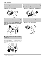
...; Sharp edges could fall with it, causing property damage, product failure, and personal injury. 4 Room Air Conditioner Safety Precautions Do not modify or extend the power cord. • There is risk of fire, electric shock, explosion, or injury. Be cautious when unpacking ...and installing the product. Gasolin Be sure the installation area does not deteriorate with age. • If the base collapses, the air conditioner could cause injury. Sharp edges • There is risk of fire or failure of the case edges and the fins on the condenser and evaporator...
...; Sharp edges could fall with it, causing property damage, product failure, and personal injury. 4 Room Air Conditioner Safety Precautions Do not modify or extend the power cord. • There is risk of fire, electric shock, explosion, or injury. Be cautious when unpacking ...and installing the product. Gasolin Be sure the installation area does not deteriorate with age. • If the base collapses, the air conditioner could cause injury. Sharp edges • There is risk of fire or failure of the case edges and the fins on the condenser and evaporator...

Service Manual
Page 5
NOTICE This symbol indicates special notes. Dimensions Outside Dimensions D W Cool Energy Saver F1 LOW 'F F2 MED F3 HIGH Fan Dry Timer TEMP MODE TIMER FAN SPEED POWER H Dimension W H D Model mm(inch) mm(inch) mm(inch) ALL MODELS 660(25 31/32) 428(16 27/32) 680(26 27/32) Service Manual 5 This symbol alerts you to the air conditioner. Dimensions Symbols Used in this Manual This symbol alerts you to hazards that could cause harm to the risk of electric shock.
NOTICE This symbol indicates special notes. Dimensions Outside Dimensions D W Cool Energy Saver F1 LOW 'F F2 MED F3 HIGH Fan Dry Timer TEMP MODE TIMER FAN SPEED POWER H Dimension W H D Model mm(inch) mm(inch) mm(inch) ALL MODELS 660(25 31/32) 428(16 27/32) 680(26 27/32) Service Manual 5 This symbol alerts you to the air conditioner. Dimensions Symbols Used in this Manual This symbol alerts you to hazards that could cause harm to the risk of electric shock.

Service Manual
Page 6
HEATING RUNNING CURRENT (A) - 9.0 - CONTROL THERMISTOR AIR DIRECTION CONTROL VERTICAL LOUVER (RIGHT & LEFT) HORIZONTAL LOUVER (UP & DOWN) CONSTRUCTION SLIDE IN-OUT CHASSIS ...the product since this specification may be changed for improving performance. 6 Room Air Conditioner INPUT (W) - 1,930 - Specfications Product Specifications ITEMS POWER SUPPLY MODELS LW1800PR LW1800ER LW1800ERZ3 LWP1830WAL LW1500PR LW1500PRY3 LWP1820PDL LWP1820PEL LWC182PLMM0 LWC212PLMM0 LW1804ER LWC183PLMD1 HBLG1803R LW1800PRZ3 1ø, 208/230V, 60Hz 1ø, 115V, 60Hz 1ø, ...
HEATING RUNNING CURRENT (A) - 9.0 - CONTROL THERMISTOR AIR DIRECTION CONTROL VERTICAL LOUVER (RIGHT & LEFT) HORIZONTAL LOUVER (UP & DOWN) CONSTRUCTION SLIDE IN-OUT CHASSIS ...the product since this specification may be changed for improving performance. 6 Room Air Conditioner INPUT (W) - 1,930 - Specfications Product Specifications ITEMS POWER SUPPLY MODELS LW1800PR LW1800ER LW1800ERZ3 LWP1830WAL LW1500PR LW1500PRY3 LWP1820PDL LWP1820PEL LWC182PLMM0 LWC212PLMM0 LW1804ER LWC183PLMD1 HBLG1803R LW1800PRZ3 1ø, 208/230V, 60Hz 1ø, 115V, 60Hz 1ø, ...
Service Manual
Page 7
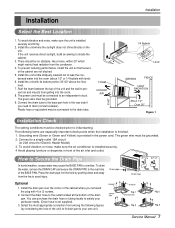
...to an independent circuit. Drain pipe Drain cap Optional CABINET SCREW 1. To avoid vibration and noise, make sure the air conditioner is finished. 1. Stuff the foam between the top of the air inlet and outlet. Connect the drain tube to the base pan hole in front of the unit and the wall... to the drain tube. FOAM COOLED AIR 30-60" 1/4 Bubble Level AWNING FENCE HEAT RADIATION About 1/2" Over 20" Figure 1 Installation Check The setting conditions must be grounded. 9. To drain the ...
...to an independent circuit. Drain pipe Drain cap Optional CABINET SCREW 1. To avoid vibration and noise, make sure the air conditioner is finished. 1. Stuff the foam between the top of the air inlet and outlet. Connect the drain tube to the base pan hole in front of the unit and the wall... to the drain tube. FOAM COOLED AIR 30-60" 1/4 Bubble Level AWNING FENCE HEAT RADIATION About 1/2" Over 20" Figure 1 Installation Check The setting conditions must be grounded. 9. To drain the ...
Service Manual
Page 8
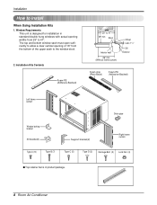
...(2) Support bracket(2) Right frame curtain Type A (14) Type B (7) Type C (5) Type D (2) Carriage Bolt (2) Lock Nut (4) s Top retainer bar is designed for installation in product package. 8 Room Air Conditioner Window Requirements This unit is in standard double hung windows with actual opening of the upper sash to 41". Installation Kits Contents Foam-PE (Adhesive...
...(2) Support bracket(2) Right frame curtain Type A (14) Type B (7) Type C (5) Type D (2) Carriage Bolt (2) Lock Nut (4) s Top retainer bar is designed for installation in product package. 8 Room Air Conditioner Window Requirements This unit is in standard double hung windows with actual opening of the upper sash to 41". Installation Kits Contents Foam-PE (Adhesive...

Service Manual
Page 10
... the center line marked window stool. 3. Installation Cabinet Installation 1. Mark a line on the bottom front with a very slight tilt downward toward the outside. 10 Room Air Conditioner Sill Bracket Carriage Bolt (M-Screw) Figure 5 Cabinet Track hole Support Bracket Carriage bolt and lock nut Figure 6 Support Bracket Lock nut Machine screw (Type D) and...
... the center line marked window stool. 3. Installation Cabinet Installation 1. Mark a line on the bottom front with a very slight tilt downward toward the outside. 10 Room Air Conditioner Sill Bracket Carriage Bolt (M-Screw) Figure 5 Cabinet Track hole Support Bracket Carriage bolt and lock nut Figure 6 Support Bracket Lock nut Machine screw (Type D) and...

Service Manual
Page 11
... the Foam-strip to each Frame curtain the window sash by inserting the tabs on the grille into the tabs on the front of room air conditioner is now completed. Attach the Window locking bracket with a screw (Type A) through the front grille. (See Fig. 14) 12. Push the grille in until it...
... the Foam-strip to each Frame curtain the window sash by inserting the tabs on the grille into the tabs on the front of room air conditioner is now completed. Attach the Window locking bracket with a screw (Type A) through the front grille. (See Fig. 14) 12. Push the grille in until it...

Service Manual
Page 12
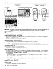
...determine if cooling is selected, the fan stops when the compressor stops cooling. Operation Operation Function of the air conditioner or if there are obstacles between the Remote Control unit and the air conditioner. Approximately every 3 minutes the fan will shift among COOL, ENERGY SAVER, FAN and DRY as follows. ...POWER BUTTON To turn the air conditioner OFF, push the button again. The temperature can automatically control the temperature of the room. OPERATION MODE SELECTION BUTTON Every time ...
...determine if cooling is selected, the fan stops when the compressor stops cooling. Operation Operation Function of the air conditioner or if there are obstacles between the Remote Control unit and the air conditioner. Approximately every 3 minutes the fan will shift among COOL, ENERGY SAVER, FAN and DRY as follows. ...POWER BUTTON To turn the air conditioner OFF, push the button again. The temperature can automatically control the temperature of the room. OPERATION MODE SELECTION BUTTON Every time ...
Service Manual
Page 14
...HBLG1803R Cool Energy Saver Fan Dry Timer F1 LOW F2 MED F3 HIGH TEMP ˚F 6 2 3 5 4 1 Precaution: The Remote Control unit will not function properly if strong light strikes the sensor window of the room. ROOM TEMPERATURE SETTING BUTTON This button can automatically control the air flow direction. 14 Room Air Conditioner... POWER BUTTON To turn the air conditioner OFF, push the button again. To turn the air conditioner ON, push the button. Every time you push ...
...HBLG1803R Cool Energy Saver Fan Dry Timer F1 LOW F2 MED F3 HIGH TEMP ˚F 6 2 3 5 4 1 Precaution: The Remote Control unit will not function properly if strong light strikes the sensor window of the room. ROOM TEMPERATURE SETTING BUTTON This button can automatically control the air flow direction. 14 Room Air Conditioner... POWER BUTTON To turn the air conditioner OFF, push the button again. To turn the air conditioner ON, push the button. Every time you push ...

Service Manual
Page 16
...right side. 4. Front Grille 1. Pull the front grille from the evaporator channel. 5. Remove the housing that connects Plazma Air Purifier.(Optional) 8. Before the following disassembly, CONTROL BOX set to remove inner screw. (Optional) 9. Open the lnlet grille downward and ... DESIRED FPFRFE32U1SENAHMRALSAIEUGOEYVTIRTDWRHFAEOGIRREYTR TIMER SPFAENED ˚C POWER ESnaCevrogeoryl Fan Dry MODE Timer TIMER FFF321HMLIGOEDWH TEMP SPFAENED ˚C POWER 16 Room Air Conditioner Figure 15 Figure 16 Figure 157 Remove the screw at left cover of filter case and open the cover to OFF...
...right side. 4. Front Grille 1. Pull the front grille from the evaporator channel. 5. Remove the housing that connects Plazma Air Purifier.(Optional) 8. Before the following disassembly, CONTROL BOX set to remove inner screw. (Optional) 9. Open the lnlet grille downward and ... DESIRED FPFRFE32U1SENAHMRALSAIEUGOEYVTIRTDWRHFAEOGIRREYTR TIMER SPFAENED ˚C POWER ESnaCevrogeoryl Fan Dry MODE Timer TIMER FFF321HMLIGOEDWH TEMP SPFAENED ˚C POWER 16 Room Air Conditioner Figure 15 Figure 16 Figure 157 Remove the screw at left cover of filter case and open the cover to OFF...

Service Manual
Page 18
... to attach the recovery system, install one (such as a WATCO A-1) before venting the FreonTM. Remove the cabinet. (Refer to the removal procedure, above . 18 Room Air Conditioner Figure 22 Figure 23 Figure 24 After purging the unit completely, unbraze the suction and discharge tubes at the compressor connections. 5. Re-install the components...
... to attach the recovery system, install one (such as a WATCO A-1) before venting the FreonTM. Remove the cabinet. (Refer to the removal procedure, above . 18 Room Air Conditioner Figure 22 Figure 23 Figure 24 After purging the unit completely, unbraze the suction and discharge tubes at the compressor connections. 5. Re-install the components...

Service Manual
Page 20
... Remove the fan. (Refer to section 4) 3. Condenser CAUTION: Discharge the refrigerant system using a FreonTM Recovery System. Remove the condenser. 6. Remove the air guide upper. (Refer to section 5) 4. Move the evaporator sideways carefully. (Refer to section 4) 3. Remove the evaporator. 7. Remove the turbo fan..... 6. Re-install the components by referring to section 3) 2. Remove the cabinet. (Refer to notes. (See Figure 29) 20 Room Air Conditioner Figure 27 Figure 28 Figure 29 If there is no valve to section 2) 2. Remove the 5 screws that fasten the brace.(Refer to ...
... Remove the fan. (Refer to section 4) 3. Condenser CAUTION: Discharge the refrigerant system using a FreonTM Recovery System. Remove the condenser. 6. Remove the air guide upper. (Refer to section 5) 4. Move the evaporator sideways carefully. (Refer to section 4) 3. Remove the evaporator. 7. Remove the turbo fan..... 6. Re-install the components by referring to section 3) 2. Remove the cabinet. (Refer to notes. (See Figure 29) 20 Room Air Conditioner Figure 27 Figure 28 Figure 29 If there is no valve to section 2) 2. Remove the 5 screws that fasten the brace.(Refer to ...

Service Manual
Page 22
CONDENSER (HIGH PRESSURE SIDE) COMPOUND GAUGE MANIFOLD GAUGE B A CAPILLARY TUBE SEE INSETS BELOW EVAPORATOR (LOW PRESSURE SIDE) COMPRESSOR A B EXTERNAL VACUUM PUMP Figure 30A-Pulling Vacuum 22 Room Air Conditioner LOW HI B A CHARGING CYLINDER C Figure 30B-Charging Disassembly Equipment needed: Vacuum pump, Charging cylinder, Manifold gauge, Brazing equipment. Pin-off tool capable of making a vapor-proof seal, Leak detector, Tubing cutter, Hand Tools to remove components, Service valve.
CONDENSER (HIGH PRESSURE SIDE) COMPOUND GAUGE MANIFOLD GAUGE B A CAPILLARY TUBE SEE INSETS BELOW EVAPORATOR (LOW PRESSURE SIDE) COMPRESSOR A B EXTERNAL VACUUM PUMP Figure 30A-Pulling Vacuum 22 Room Air Conditioner LOW HI B A CHARGING CYLINDER C Figure 30B-Charging Disassembly Equipment needed: Vacuum pump, Charging cylinder, Manifold gauge, Brazing equipment. Pin-off tool capable of making a vapor-proof seal, Leak detector, Tubing cutter, Hand Tools to remove components, Service valve.

Service Manual
Page 24
Schematic Diagram 24 Room Air Conditioner CN-TELE SMW200-03 (RD) 33 22 11 5V C01T 0.1 50V PIPE-TH CN-TH2 SMW250-02 11 22 C02T 0.001 D01T 1N4148 Q04T A104M ... 5V C05D + C06D 220 0.01 10V 50V 11 12V 12 CN-AC/DC 5V 51581-12(YEONHO) 52044-1245(MOLEX) ANGLE RY-COMP G4A-1A-E-LG ZNR01J SVC271D-14A SVC271D-14A FUSE 250V/T2A POWER TRANS 1 7 D02D D05D 2 D03D 4 D04D + C01D D02D~D05D 1000 1N4004 35V 12V IC01D O I 7812 + C02D C03D...
Schematic Diagram 24 Room Air Conditioner CN-TELE SMW200-03 (RD) 33 22 11 5V C01T 0.1 50V PIPE-TH CN-TH2 SMW250-02 11 22 C02T 0.001 D01T 1N4148 Q04T A104M ... 5V C05D + C06D 220 0.01 10V 50V 11 12V 12 CN-AC/DC 5V 51581-12(YEONHO) 52044-1245(MOLEX) ANGLE RY-COMP G4A-1A-E-LG ZNR01J SVC271D-14A SVC271D-14A FUSE 250V/T2A POWER TRANS 1 7 D02D D05D 2 D03D 4 D04D + C01D D02D~D05D 1000 1N4004 35V 12V IC01D O I 7812 + C02D C03D...

Service Manual
Page 26
...TEMP DOWN RECEIVER IC01A SW06G TEMP UP C02L C02A BZ01E J21 J22 J23 J2ZD02F ZD01F SW03G POWER J24 26 Room Air Conditioner s MODEL: LWC182PLMM0/LWC212PLMM0 LW1800ERZ3/HBLG1803R Schematic Diagram Components Location s MODEL: LW1800PR/LW1800ER LW1500PR/LWP1830WAL LWP1820PDL/LWP1820PEL LW1800ERZ3/LW1804ER LWC183PLMD1 D02D D03D D04D D05D IC01D... C04D J2 QIC02DT RY-MED J3 RY-HI Q04T J6 D01T C02T J7 s MODEL: LWC182PLMM0/LWC212PLMM0 LW1500PRY3/LW1800PRZ3 HBLG1803R CN-TELE CN-TH2 POWER TRANS FUSE CN-PWR ZNR01J R01J E03J J8 E04J CN-MOTOR E02J E05J E01J CN-4WAY C01J 2....
...TEMP DOWN RECEIVER IC01A SW06G TEMP UP C02L C02A BZ01E J21 J22 J23 J2ZD02F ZD01F SW03G POWER J24 26 Room Air Conditioner s MODEL: LWC182PLMM0/LWC212PLMM0 LW1800ERZ3/HBLG1803R Schematic Diagram Components Location s MODEL: LW1800PR/LW1800ER LW1500PR/LWP1830WAL LWP1820PDL/LWP1820PEL LW1800ERZ3/LW1804ER LWC183PLMD1 D02D D03D D04D D05D IC01D... C04D J2 QIC02DT RY-MED J3 RY-HI Q04T J6 D01T C02T J7 s MODEL: LWC182PLMM0/LWC212PLMM0 LW1500PRY3/LW1800PRZ3 HBLG1803R CN-TELE CN-TH2 POWER TRANS FUSE CN-PWR ZNR01J R01J E03J J8 E04J CN-MOTOR E02J E05J E01J CN-4WAY C01J 2....

Service Manual
Page 28
... Figure 31 is called the refrigeration system. ROOM AIR CONITIONER CYCLE OF REFRIGERATION EVAPORATOR COILS COOLED AIR COMPLETE LIQUID BOIL OFF POINT SUCTION LINE COOL LOW PRESSURE VAPOR ROOM AIR HEAT LOAD CONDENSER COILS VAPOR INLET HOT DISCHARGED AIR LIQUID PRESSURE DROP 28 Room Air Conditioner MOTOR OUTSIDE COOLING AIR FOR REFRIGERANT PASS THROUGH COMPRESSOR OIL (LIQUID...
... Figure 31 is called the refrigeration system. ROOM AIR CONITIONER CYCLE OF REFRIGERATION EVAPORATOR COILS COOLED AIR COMPLETE LIQUID BOIL OFF POINT SUCTION LINE COOL LOW PRESSURE VAPOR ROOM AIR HEAT LOAD CONDENSER COILS VAPOR INLET HOT DISCHARGED AIR LIQUID PRESSURE DROP 28 Room Air Conditioner MOTOR OUTSIDE COOLING AIR FOR REFRIGERANT PASS THROUGH COMPRESSOR OIL (LIQUID...

Service Manual
Page 30
.... Irregular motor resistance ( ). Check circuit breaker and fuse. Defect of compressor capacitor. Irregular motor resistance ( ) Irregular motor insulation ( ) Replacement of compressor (Motor damaged) 30 Room Air Conditioner Regular but fails to Start Check of control switch setting. Replacement of compressor (locking of fan motor. Troubleshooting Guide Fails to start. Fan only fails...
.... Irregular motor resistance ( ). Check circuit breaker and fuse. Defect of compressor capacitor. Irregular motor resistance ( ) Irregular motor insulation ( ) Replacement of compressor (Motor damaged) 30 Room Air Conditioner Regular but fails to Start Check of control switch setting. Replacement of compressor (locking of fan motor. Troubleshooting Guide Fails to start. Fan only fails...

Service Manual
Page 32
...-COMP OK? YES • Check the RY-COMP. • Check the wiring Diagram. Possible Trouble 3 The compressor always operate. to RY-COMP again. 32 Room Air Conditioner YES • Wait 3 Minutes. • Replace MAIN PCB Ass'y. Troubleshooting Guide Possible Trouble 2 The compressor does not operate. Is setting Temp. Is the voltage N0...
...-COMP OK? YES • Check the RY-COMP. • Check the wiring Diagram. Possible Trouble 3 The compressor always operate. to RY-COMP again. 32 Room Air Conditioner YES • Wait 3 Minutes. • Replace MAIN PCB Ass'y. Troubleshooting Guide Possible Trouble 2 The compressor does not operate. Is setting Temp. Is the voltage N0...


