Service Manual
Page 4
... 17 9-2. TEST 3 MOTOR TEST 19 9-4. TEST 5 DOOR SWITCH TEST 21 9-6. TEST 7 GAS VALVE TEST - CABINET & DOOR ASSEMBLY 33 12-3-1. FEATURES AND BENEFITS ...5 3. DIAGNOSTIC TEST ...16 9-1. DISASSEMBLY INSTRUCTIONS 26 12. DRUM & MOTOR ASSEMBLY : ELECTRIC TYPE 34 12-3-2. INSTALLATION INSTRUCTIONS 6 4. TEST 2 THERMISTOR TEST --- ELECTRIC TYPE 22 9-7. GAS TYPE 23 10. EXPLODED VIEW ...32...
... 17 9-2. TEST 3 MOTOR TEST 19 9-4. TEST 5 DOOR SWITCH TEST 21 9-6. TEST 7 GAS VALVE TEST - CABINET & DOOR ASSEMBLY 33 12-3-1. FEATURES AND BENEFITS ...5 3. DIAGNOSTIC TEST ...16 9-1. DISASSEMBLY INSTRUCTIONS 26 12. DRUM & MOTOR ASSEMBLY : ELECTRIC TYPE 34 12-3-2. INSTALLATION INSTRUCTIONS 6 4. TEST 2 THERMISTOR TEST --- ELECTRIC TYPE 22 9-7. GAS TYPE 23 10. EXPLODED VIEW ...32...
Service Manual
Page 25
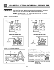
10 CHANGE GAS SETTING (NATURAL GAS, PROPANE GAS) ! Propane Gas Orifice is set. Disassemble the pipe assembly. Conversion must be made by a qualified technician. STEP 1 : VALVE SETTING Full open "Change screw" STEP 2 : ORIFICE CHANGE Orifice Close "Change screw" Remove 2 ...
10 CHANGE GAS SETTING (NATURAL GAS, PROPANE GAS) ! Propane Gas Orifice is set. Disassemble the pipe assembly. Conversion must be made by a qualified technician. STEP 1 : VALVE SETTING Full open "Change screw" STEP 2 : ORIFICE CHANGE Orifice Close "Change screw" Remove 2 ...
Service Manual
Page 27
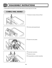
Pull the control panel forward. 3. 11 DISASSEMBLY INSTRUCTIONS Disassemble and repair the unit only after pulling out power plug from the outlet. 1. Remove 3 screws on the rear Panel. 2. Open the cover protect. 4. Disconnect connectors. 5. Remove 5 screws. 6. Disassemble the controller assembly. 26
Pull the control panel forward. 3. 11 DISASSEMBLY INSTRUCTIONS Disassemble and repair the unit only after pulling out power plug from the outlet. 1. Remove 3 screws on the rear Panel. 2. Open the cover protect. 4. Disconnect connectors. 5. Remove 5 screws. 6. Disassemble the controller assembly. 26
Service Manual
Page 29
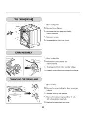
... through front of dryer. 1. Remove the screw holding the drum lamp shield in place. 3. Remove Cover Cabinet. 3. Disconnect the door lamp and electro sensor connector. 4. Disassemble the Tub Drum [Front]. -1 1. Slide the shield up and remove. 4. Replace the lamp shield and screw. 28 Remove 4 screws. 5. Remove the Cover Cabinet and Tub...
... through front of dryer. 1. Remove the screw holding the drum lamp shield in place. 3. Remove Cover Cabinet. 3. Disconnect the door lamp and electro sensor connector. 4. Disassemble the Tub Drum [Front]. -1 1. Slide the shield up and remove. 4. Replace the lamp shield and screw. 28 Remove 4 screws. 5. Remove the Cover Cabinet and Tub...


