
Owner's Manual
Page 10
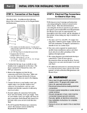
... only if allowed by your laundry room's gas supply. Securely tighten all electrical connections • See installation instructions for checking inlet gas pressure) 3. The wiring diagram is important that you thoroughly review that you remove the shipping cap. 3. For LP (Liquefied Petroleum) gas connection, refer to manual section on Electrical Requirements...
... only if allowed by your laundry room's gas supply. Securely tighten all electrical connections • See installation instructions for checking inlet gas pressure) 3. The wiring diagram is important that you thoroughly review that you remove the shipping cap. 3. For LP (Liquefied Petroleum) gas connection, refer to manual section on Electrical Requirements...
Owner's Manual
Page 13
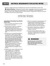
... and dryer terminal block IS NOT supplied with instructions mentioned on next page. Type of pigtail and gauge of different voltage than that the wiring diagram is provided inside the dryer control hood. Refer to the equipment-grounding terminal or lead on the dryer. f) The method of your Electric Electric Dryer...
... and dryer terminal block IS NOT supplied with instructions mentioned on next page. Type of pigtail and gauge of different voltage than that the wiring diagram is provided inside the dryer control hood. Refer to the equipment-grounding terminal or lead on the dryer. f) The method of your Electric Electric Dryer...
Owner's Manual
Page 18
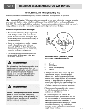
The plug should be plugged directed into a properly installed outlet that the wiring diagram is rated 120 Volts AC (alternating current) 15 Amps. Electrical Requirements for Your Dryer: a) Please note that is grounded in accordance with all applicable local ...
The plug should be plugged directed into a properly installed outlet that the wiring diagram is rated 120 Volts AC (alternating current) 15 Amps. Electrical Requirements for Your Dryer: a) Please note that is grounded in accordance with all applicable local ...
Owner's Manual
Page 21
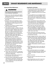
... reach places. This Kit comes in hard to ensure the dampers are moving freely, that the dampers are not pushed in and that the wiring diagram is provided inside the dryer control hood. Clean the control panel with a clean towel, firmly replace the lint screen in the event any lint off...
... reach places. This Kit comes in hard to ensure the dampers are moving freely, that the dampers are not pushed in and that the wiring diagram is provided inside the dryer control hood. Clean the control panel with a clean towel, firmly replace the lint screen in the event any lint off...
Service Manual
Page 4
...26 12. EXPLODED VIEW ...32 12-1. COLUMBUS DRYER CYCLE PROCESS 9 5. OUT ...14 8. ELECTRIC TYPE 22 9-7. INSTALLATION INSTRUCTIONS 6 4. MOTOR DIAGRAM AND SCHEMATIC 13 7. CHANGE GAS SETTING (NATURAL GAS, PROPANE GAS 24 11. DRUM & MOTOR ASSEMBLY : GAS TYPE 35 13. CONTENTS ...1. CONTROL PANEL & PLATE ASSEMBLY 32 12-2. DRUM & MOTOR ASSEMBLY : ELECTRIC TYPE 34 12-3-2. SPECIFICATIONS ...4 2. TEST 6 HEATER SWITCH TEST - WIRING DIAGRAM ...15 9. DIAGNOSTIC TEST ...16 9-1. GAS TYPE 23 10. TEST 7 GAS VALVE TEST - REPLACEMENT PARTS LIST 36 3 CONTROL LAY - TEST 1 ...
...26 12. EXPLODED VIEW ...32 12-1. COLUMBUS DRYER CYCLE PROCESS 9 5. OUT ...14 8. ELECTRIC TYPE 22 9-7. INSTALLATION INSTRUCTIONS 6 4. MOTOR DIAGRAM AND SCHEMATIC 13 7. CHANGE GAS SETTING (NATURAL GAS, PROPANE GAS 24 11. DRUM & MOTOR ASSEMBLY : GAS TYPE 35 13. CONTENTS ...1. CONTROL PANEL & PLATE ASSEMBLY 32 12-2. DRUM & MOTOR ASSEMBLY : ELECTRIC TYPE 34 12-3-2. SPECIFICATIONS ...4 2. TEST 6 HEATER SWITCH TEST - WIRING DIAGRAM ...15 9. DIAGNOSTIC TEST ...16 9-1. GAS TYPE 23 10. TEST 7 GAS VALVE TEST - REPLACEMENT PARTS LIST 36 3 CONTROL LAY - TEST 1 ...
Service Manual
Page 14
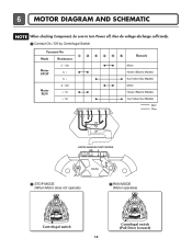
Contact On / Off by Centrifugal Switch STOP MODE (When Motor does not operate) RUN MODE (Motor operates) Centrifugal switch Centrifugal switch (Pull Drive forward) 13 6 MOTOR DIAGRAM AND SCHEMATIC NOTE When checking Component, be sure to turn Power off, then do voltage discharge sufficiently.
Contact On / Off by Centrifugal Switch STOP MODE (When Motor does not operate) RUN MODE (Motor operates) Centrifugal switch Centrifugal switch (Pull Drive forward) 13 6 MOTOR DIAGRAM AND SCHEMATIC NOTE When checking Component, be sure to turn Power off, then do voltage discharge sufficiently.
Service Manual
Page 16
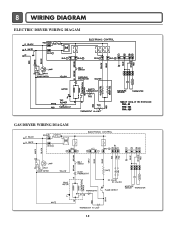
8 WIRING DIAGRAM ELECTRIC DRYER WIRING DIAGAM GAS DRYER WIRING DIAGAM 15
8 WIRING DIAGRAM ELECTRIC DRYER WIRING DIAGAM GAS DRYER WIRING DIAGAM 15
Service Manual
Page 20
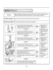
... below 3Ω between Idler Switch terminals? No Heater will function; " (Yellow wire)? " (Brown wire)? Test 3 Motor test Caution Before measuring resistance, be sure to 'Motor Diagram & Check') • Check if Control Connector is contacted. 19 " (White wire) and "BL2- Is resistance below 1Ω between Connector "BL2-
... below 3Ω between Idler Switch terminals? No Heater will function; " (Yellow wire)? " (Brown wire)? Test 3 Motor test Caution Before measuring resistance, be sure to 'Motor Diagram & Check') • Check if Control Connector is contacted. 19 " (White wire) and "BL2- Is resistance below 1Ω between Connector "BL2-

