
Owner's Manual
Page 10
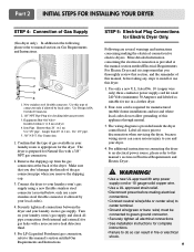
... by local codes. More detailed information concerning the electrical connection is provided at the back of gas available in fire or electrical shock. 9 The wiring diagram is important that you thoroughly review that the type of the dryer.
... by local codes. More detailed information concerning the electrical connection is provided at the back of gas available in fire or electrical shock. 9 The wiring diagram is important that you thoroughly review that the type of the dryer.
Owner's Manual
Page 13
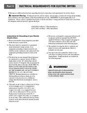
.... b) This dryer must be moved from its own terminal block that listed on both sides of your Electric Electric Dryer: a) Please note that the wiring diagram is optional and subject to you and your dryer according to operate the dryer. 120V/208V, 60 Hertz, 3-Wire Installation 120V/ 240V, 60 Hertz, 3-Wire...
.... b) This dryer must be moved from its own terminal block that listed on both sides of your Electric Electric Dryer: a) Please note that the wiring diagram is optional and subject to you and your dryer according to operate the dryer. 120V/208V, 60 Hertz, 3-Wire Installation 120V/ 240V, 60 Hertz, 3-Wire...
Owner's Manual
Page 18
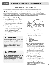
Please contact a qualified electrician to check your dryer. Electrical Requirements for any adapter to allow additional cords to connect to ensure that the wiring diagram is provided inside the dryer control hood. WARNING! b) Your dryer is rated 120 Volts AC (alternating current) 15 Amps. Do not overload the circuit by ...
Please contact a qualified electrician to check your dryer. Electrical Requirements for any adapter to allow additional cords to connect to ensure that the wiring diagram is provided inside the dryer control hood. WARNING! b) Your dryer is rated 120 Volts AC (alternating current) 15 Amps. Do not overload the circuit by ...
Owner's Manual
Page 21
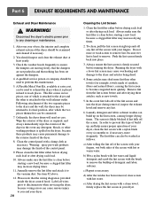
..., because wiring errors can cause serious injury to ensure the dampers are moving freely, that the dampers are not pushed in and that the wiring diagram is clean before drying each load or after drying these products may increase drying times. 2. Clean the lint filter either before starting a new load, because...
..., because wiring errors can cause serious injury to ensure the dampers are moving freely, that the dampers are not pushed in and that the wiring diagram is clean before drying each load or after drying these products may increase drying times. 2. Clean the lint filter either before starting a new load, because...
Service Manual
Page 4
...1 120VAC ELECTRICAL SUPPLY 17 9-2. TEST 6 HEATER SWITCH TEST - EXPLODED VIEW ...32 12-1. REPLACEMENT PARTS LIST 36 3 CONTENTS 1. MOTOR DIAGRAM AND SCHEMATIC 13 7. TEST 4 MOISTURE SENSOR 20 9-5. CHANGE GAS SETTING (NATURAL GAS, PROPANE GAS 24 11. INSTALLATION INSTRUCTIONS 6 4. ...SPECIFICATIONS ...4 2. FEATURES AND BENEFITS ...5 3. OUT ...14 8. WIRING DIAGRAM ...15 9. TEST 2 THERMISTOR TEST --- TEST 5 DOOR SWITCH TEST 21 9-6. ELECTRIC TYPE 22 9-7. GAS TYPE 23 10. DISASSEMBLY...
...1 120VAC ELECTRICAL SUPPLY 17 9-2. TEST 6 HEATER SWITCH TEST - EXPLODED VIEW ...32 12-1. REPLACEMENT PARTS LIST 36 3 CONTENTS 1. MOTOR DIAGRAM AND SCHEMATIC 13 7. TEST 4 MOISTURE SENSOR 20 9-5. CHANGE GAS SETTING (NATURAL GAS, PROPANE GAS 24 11. INSTALLATION INSTRUCTIONS 6 4. ...SPECIFICATIONS ...4 2. FEATURES AND BENEFITS ...5 3. OUT ...14 8. WIRING DIAGRAM ...15 9. TEST 2 THERMISTOR TEST --- TEST 5 DOOR SWITCH TEST 21 9-6. ELECTRIC TYPE 22 9-7. GAS TYPE 23 10. DISASSEMBLY...
Service Manual
Page 14
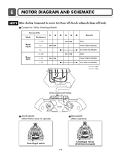
6 MOTOR DIAGRAM AND SCHEMATIC NOTE When checking Component, be sure to turn Power off, then do voltage discharge sufficiently. Contact On / Off by Centrifugal Switch STOP MODE (When Motor does not operate) RUN MODE (Motor operates) Centrifugal switch Centrifugal switch (Pull Drive forward) 13
6 MOTOR DIAGRAM AND SCHEMATIC NOTE When checking Component, be sure to turn Power off, then do voltage discharge sufficiently. Contact On / Off by Centrifugal Switch STOP MODE (When Motor does not operate) RUN MODE (Motor operates) Centrifugal switch Centrifugal switch (Pull Drive forward) 13
Service Manual
Page 16
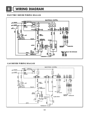
8 WIRING DIAGRAM ELECTRIC DRYER WIRING DIAGAM GAS DRYER WIRING DIAGAM 15
8 WIRING DIAGRAM ELECTRIC DRYER WIRING DIAGAM GAS DRYER WIRING DIAGAM 15
Service Manual
Page 20
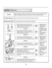
...; Drum Belt cuts off • Drum Belt takes off , and do voltage discharge. (When discharging, contact the metal plug of Outlet Thermostat attached to 'Motor Diagram & Check') • Check if Control Connector is closed . Test 3 Motor test Caution Before measuring resistance, be sure to Motor Bracket operate Level by drum belt...
...; Drum Belt cuts off • Drum Belt takes off , and do voltage discharge. (When discharging, contact the metal plug of Outlet Thermostat attached to 'Motor Diagram & Check') • Check if Control Connector is closed . Test 3 Motor test Caution Before measuring resistance, be sure to Motor Bracket operate Level by drum belt...

