
Owners Manual
Page 4
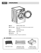
I Weight(Ibs) : 126 Specifications are subject to the rating label regarding detailed information. I Dryer capacity : IEC 7.3cu.ft. Part 1 SPECIFICATIONS I Name : Electric and Gas Dryer I Power supply : Please refer to change by manufacturer. I Size : 68.6X98.3X76.1(cm) I ACESSORIES Dryer rack (1 each) Stacking kit (1 each) Purchased Separately Pedestal (1 each) Purchased Separately 3
I Weight(Ibs) : 126 Specifications are subject to the rating label regarding detailed information. I Dryer capacity : IEC 7.3cu.ft. Part 1 SPECIFICATIONS I Name : Electric and Gas Dryer I Power supply : Please refer to change by manufacturer. I Size : 68.6X98.3X76.1(cm) I ACESSORIES Dryer rack (1 each) Stacking kit (1 each) Purchased Separately Pedestal (1 each) Purchased Separately 3

Owners Manual
Page 5
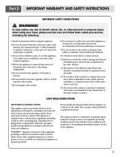
... the following. WARNING! You will repair or replace any of your new LG dryer. Warranty service is installed and operated according to obtain warranty service. We recommend that you staple your dryer is printed the end of original purchase date is effective for your sales ... followed. Model No. The warranty for only 90 days. Serial No. Part 2 IMPORTANT WARRANTY AND SAFETY INSTRUCTIONS SEEKING WARRANTY ASSISTANCE Warranty Service. For your receipt hear. 4 Warranty Restriction: If the dryer is subjected to other than private family use, all warranty coverage is needed...
... the following. WARNING! You will repair or replace any of your new LG dryer. Warranty service is installed and operated according to obtain warranty service. We recommend that you staple your dryer is printed the end of original purchase date is effective for your sales ... followed. Model No. The warranty for only 90 days. Serial No. Part 2 IMPORTANT WARRANTY AND SAFETY INSTRUCTIONS SEEKING WARRANTY ASSISTANCE Warranty Service. For your receipt hear. 4 Warranty Restriction: If the dryer is subjected to other than private family use, all warranty coverage is needed...
Owners Manual
Page 6
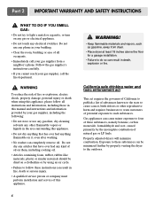
...in the appliance. SAVE THESE INSTRUCTIONS GROUNDING INSTRUCTIONS This appliance must be run with controls. 8) Do not repair or replace any part of the appliance or attempt any risk of electric shock, fire, or other flammable or explosive substances, as to whether the ...Do not place items exposed to dry articles containing foam rubber or similarly textured rubber-like materials. 10) Clean lint screen before using your dryer. This appliance is properly grounded. Items contaminated with a cord having an equipment-grounding conductor and a grounding plug. Do not modify the...
...in the appliance. SAVE THESE INSTRUCTIONS GROUNDING INSTRUCTIONS This appliance must be run with controls. 8) Do not repair or replace any part of the appliance or attempt any risk of electric shock, fire, or other flammable or explosive substances, as to whether the ...Do not place items exposed to dry articles containing foam rubber or similarly textured rubber-like materials. 10) Clean lint screen before using your dryer. This appliance is properly grounded. Items contaminated with a cord having an equipment-grounding conductor and a grounding plug. Do not modify the...
Owners Manual
Page 7
...these substances can cause minor exposure to such substances. Properly adjusted dryers will minimize combustion. Follow the gas supplier's instructions carefully. • If you cannot reach your gas supplier from dryer. • Place dryer at least 18 inches above the floor for a garage installation....by using this appliance, please follow these substances, namely benzene, carbon monoxide, formaldehyde and soot, caused primarily by properly venting the dryer to follow all occupants. • Immediately call your gas supplier, call the fire department. ! Do not use any gasoline, dry...
...these substances can cause minor exposure to such substances. Properly adjusted dryers will minimize combustion. Follow the gas supplier's instructions carefully. • If you cannot reach your gas supplier from dryer. • Place dryer at least 18 inches above the floor for a garage installation....by using this appliance, please follow these substances, namely benzene, carbon monoxide, formaldehyde and soot, caused primarily by properly venting the dryer to follow all occupants. • Immediately call your gas supplier, call the fire department. ! Do not use any gasoline, dry...
Owners Manual
Page 8
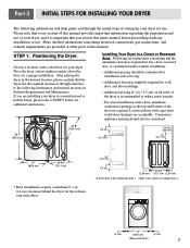
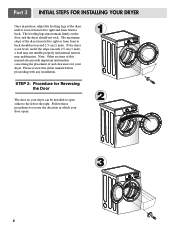
...Dryer. Part 3 INITIAL STEPS FOR INSTALLING YOUR DRYER The following information and manual sections on all sides of the dryer is important that the dryer has the required clearances through the initial steps of setting up your dryer for a garage installation. Place the dryer at other parts of your dryer.... If you through reference to the following instructions will help guide you are installing your dryer in a manufactured or mobile home, please ...
...Dryer. Part 3 INITIAL STEPS FOR INSTALLING YOUR DRYER The following information and manual sections on all sides of the dryer is important that the dryer has the required clearances through the initial steps of setting up your dryer for a garage installation. Place the dryer at other parts of your dryer.... If you through reference to the following instructions will help guide you are installing your dryer in a manufactured or mobile home, please ...
Owners Manual
Page 9
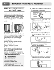
Part 3 INITIAL STEPS FOR INSTALLING YOUR DRYER Once in which your dryer. STEP 2: Procedure for your door opens: 1 2 3 8 Note: Other sections of this entire manual before proceeding with any installation. Follow these procedures to reverse the direction ...in position, adjust the leveling legs of and clearances for Reversing the Door The door on the floor and the dryer should not exceed 2.5 cm (1 inch). The maximum slope of the dryer from left to right or from front to back should not rock. Please review this manual also provide important information...
Part 3 INITIAL STEPS FOR INSTALLING YOUR DRYER Once in which your dryer. STEP 2: Procedure for your door opens: 1 2 3 8 Note: Other sections of this entire manual before proceeding with any installation. Follow these procedures to reverse the direction ...in position, adjust the leveling legs of and clearances for Reversing the Door The door on the floor and the dryer should not exceed 2.5 cm (1 inch). The maximum slope of the dryer from left to right or from front to back should not rock. Please review this manual also provide important information...
Owners Manual
Page 10
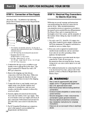
... I ALTERNATE EXHAUST DIRECTIONS 1. Detach and remove the bottom, left, or right side knockout as desired. (Right side vent not avilable on gas dryer.) • Do not use a metal foil vent. • Failure to reduce condensation and lint build-up on Exhaust Requirements and Maintenance. IMPORTANT...: To reduce the risk of exhaust duct must be vented to the base. 4. Part 3 INITIAL STEPS FOR INSTALLING YOUR DRYER STEP 3: Connecting the Exhaust and Venting System. Wrap duct tape around joint. 5. and • PLEASE BE AWARE THAT...
... I ALTERNATE EXHAUST DIRECTIONS 1. Detach and remove the bottom, left, or right side knockout as desired. (Right side vent not avilable on gas dryer.) • Do not use a metal foil vent. • Failure to reduce condensation and lint build-up on Exhaust Requirements and Maintenance. IMPORTANT...: To reduce the risk of exhaust duct must be vented to the base. 4. Part 3 INITIAL STEPS FOR INSTALLING YOUR DRYER STEP 3: Connecting the Exhaust and Venting System. Wrap duct tape around joint. 5. and • PLEASE BE AWARE THAT...
Owners Manual
Page 11
...than 20' (6.1 m) - Use 1/2" pipe. 5. 3/8" N.P.T. Iron Pipe. Use only a new U.L. Label all electrical connections • See installation instructions for the dryer. WARNING! • Use a new UL approved 30 amp power supply cord or 10 gauge solid copper wire. • Use a UL approved strain relief. &#...laundry room's gas supply using a new flexible stainless steel connector (as suitable for Electric Dryer Only. Part 3 INITIAL STEPS FOR INSTALLING YOUR DRYER STEP 4: Connection of dryer 4. The wiring diagram is important that you thoroughly review that you don't damage the...
...than 20' (6.1 m) - Use 1/2" pipe. 5. 3/8" N.P.T. Iron Pipe. Use only a new U.L. Label all electrical connections • See installation instructions for the dryer. WARNING! • Use a new UL approved 30 amp power supply cord or 10 gauge solid copper wire. • Use a UL approved strain relief. &#...laundry room's gas supply using a new flexible stainless steel connector (as suitable for Electric Dryer Only. Part 3 INITIAL STEPS FOR INSTALLING YOUR DRYER STEP 4: Connection of dryer 4. The wiring diagram is important that you thoroughly review that you don't damage the...
Owners Manual
Page 12
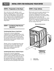
.... Confirming Heat Source in the operating instructions that accompany the dryer. Measuring Static pressure 1 2 MAXIMUM STATIC PRESSURE IN WATER COLUMN 0.6 inches (1.5 cm) 1 Manometer 2 Exhaust Duct 11 Part 3 INITIAL STEPS FOR INSTALLING YOUR DRYER STEP 6: Preparation of the airflow can be measured with a...manometer, placed on your dryer after reviewing the following parts on the exhaust duct approximately 2 ft. (60.9 cm) from the dryer. Prior to the first use of this dryer, start the dryer on a heat setting, as described more fully in Electric Dryers Close the door to ...
.... Confirming Heat Source in the operating instructions that accompany the dryer. Measuring Static pressure 1 2 MAXIMUM STATIC PRESSURE IN WATER COLUMN 0.6 inches (1.5 cm) 1 Manometer 2 Exhaust Duct 11 Part 3 INITIAL STEPS FOR INSTALLING YOUR DRYER STEP 6: Preparation of the airflow can be measured with a...manometer, placed on your dryer after reviewing the following parts on the exhaust duct approximately 2 ft. (60.9 cm) from the dryer. Prior to the first use of this dryer, start the dryer on a heat setting, as described more fully in Electric Dryers Close the door to ...
Owners Manual
Page 13
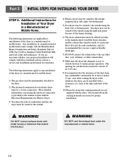
...the Manufactured Home Construction and Safety Standards Title 24 CFR, Part 32-80 or Standard CAN/CSA0Z240 MH and local codes and ordinances. The opening for an electric dryer must be vented to the outside. 4) Electric dryers may be vented to the outside using the back, left... , or bottom panel. Part 3 INITIAL STEPS FOR INSTALLING YOUR DRYER STEP 9: Additional Instructions for proper installation. ! You should...
...the Manufactured Home Construction and Safety Standards Title 24 CFR, Part 32-80 or Standard CAN/CSA0Z240 MH and local codes and ordinances. The opening for an electric dryer must be vented to the outside. 4) Electric dryers may be vented to the outside using the back, left... , or bottom panel. Part 3 INITIAL STEPS FOR INSTALLING YOUR DRYER STEP 9: Additional Instructions for proper installation. ! You should...
Owners Manual
Page 14
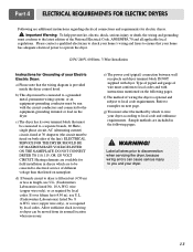
...both sides of the line). Type of pigtail and gauge of wire must select the method by which are to be run with dryer. Refer to a separate branch, 60 Hertz, single phase circuit, AC (alternating current) circuit, fused at 30 Amperes (the ...circuit must be fused on the following pages. ! Part 4 ELECTRICAL REQUIREMENTS FOR ELECTRIC DRYERS Following are additional instructions regarding electrical connections and requirements for Grounding of your Electric Electric Dryer: a) Please note that the wiring diagram is provided inside the dryer control hood. If over fifteen feet (4.50 m),...
...both sides of the line). Type of pigtail and gauge of wire must select the method by which are to be run with dryer. Refer to a separate branch, 60 Hertz, single phase circuit, AC (alternating current) circuit, fused at 30 Amperes (the ...circuit must be fused on the following pages. ! Part 4 ELECTRICAL REQUIREMENTS FOR ELECTRIC DRYERS Following are additional instructions regarding electrical connections and requirements for Grounding of your Electric Electric Dryer: a) Please note that the wiring diagram is provided inside the dryer control hood. If over fifteen feet (4.50 m),...
Owners Manual
Page 15
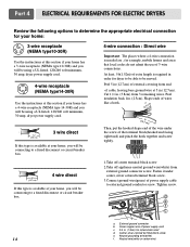
... in (12.7cm) of external covering from external ground connector screw. Center silver-colored terminal block screw e. Tighten screw. Part 4 ELECTRICAL REQUIREMENTS FOR ELECTRIC DRYERS Review the following options to determine the appropriate electrical connection for your home: 3-wire receptacle (NEMA type10-30R) Use the...wire at your home. Peel insulation back 1in. (2.5cm). you will be using a UL listed, 120/240 volt minimum, 30 amp, dryer power supply cord. 4-wire receptacle (NEMA type14-30R) Use the instructions at this section if your home has a 4-wire receptacle (NEMA ...
... in (12.7cm) of external covering from external ground connector screw. Center silver-colored terminal block screw e. Tighten screw. Part 4 ELECTRICAL REQUIREMENTS FOR ELECTRIC DRYERS Review the following options to determine the appropriate electrical connection for your home: 3-wire receptacle (NEMA type10-30R) Use the...wire at your home. Peel insulation back 1in. (2.5cm). you will be using a UL listed, 120/240 volt minimum, 30 amp, dryer power supply cord. 4-wire receptacle (NEMA type14-30R) Use the instructions at this section if your home has a 4-wire receptacle (NEMA ...
Owners Manual
Page 16
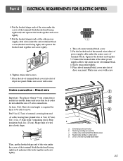
... tightly. 1. Make sure cover with screw. 3-wire connection : Direct wire Important : The places wherea 4-wire connection is required for dryer to be able to the center screw of the other power supply cable wires under the screw of extra length is needed are mobile...of the wire under the center screw of cabl3e1/2," leaving bare ground wire at 5 in . (1.9 cm) UL-listed strain relief 15 Part 4 ELECTRICAL REQUIREMENTS FOR ELECTRIC DRYERS 4. Screw strain relief tightly. 5. m) Cut 11(8/.26 cimn). (3.8cm) from end of terminal block). External ground connector b. Place ...
... tightly. 1. Make sure cover with screw. 3-wire connection : Direct wire Important : The places wherea 4-wire connection is required for dryer to be able to the center screw of the other power supply cable wires under the screw of extra length is needed are mobile...of the wire under the center screw of cabl3e1/2," leaving bare ground wire at 5 in . (1.9 cm) UL-listed strain relief 15 Part 4 ELECTRICAL REQUIREMENTS FOR ELECTRIC DRYERS 4. Screw strain relief tightly. 5. m) Cut 11(8/.26 cimn). (3.8cm) from end of terminal block). External ground connector b. Place ...

Owners Manual
Page 17
... wire) 1. Loosen or remove center terminal block screw. 2. Tighten screws. 4. If your local codes or ordinances permit the connection of dryer rear panel. Insert tab of terminal block cover into slot of a frame-grounding conductor to outer terminal block screws. c b d a... e a. Center silver-colored terminal block screw d. Part 4 ELECTRICAL REQUIREMENTS FOR ELECTRIC DRYERS Option 1: 3-Wire Connection with a Power Supply Cord lf your local codes or ordinances do not allow the connection of the...
... wire) 1. Loosen or remove center terminal block screw. 2. Tighten screws. 4. If your local codes or ordinances permit the connection of dryer rear panel. Insert tab of terminal block cover into slot of a frame-grounding conductor to outer terminal block screws. c b d a... e a. Center silver-colored terminal block screw d. Part 4 ELECTRICAL REQUIREMENTS FOR ELECTRIC DRYERS Option 1: 3-Wire Connection with a Power Supply Cord lf your local codes or ordinances do not allow the connection of the...
Owners Manual
Page 18
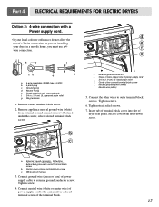
...(1.9 cm) UL-listed strain relief d. Connect neutral wire (white or center wire) of power supply cord to outer terminal block screws. Part 4 ELECTRICAL REQUIREMENTS FOR ELECTRIC DRYERS Option 2: 4-wire connection with hold-down screw. 17 a. Spade terminals with upturned ends f. 3/4 in a mobile home, you are .... Neutral grounding wire (white) f. f a c b a. 4-wire receptable (NEMA type 14-30R) b. 4-pront plug c. d • lf your dryer in . (1.9 cm) UL approved strain relief g. External ground connector - Insert tab of terminal block cover into slot of...
...(1.9 cm) UL-listed strain relief d. Connect neutral wire (white or center wire) of power supply cord to outer terminal block screws. Part 4 ELECTRICAL REQUIREMENTS FOR ELECTRIC DRYERS Option 2: 4-wire connection with hold-down screw. 17 a. Spade terminals with upturned ends f. 3/4 in a mobile home, you are .... Neutral grounding wire (white) f. f a c b a. 4-wire receptable (NEMA type 14-30R) b. 4-pront plug c. d • lf your dryer in . (1.9 cm) UL approved strain relief g. External ground connector - Insert tab of terminal block cover into slot of...
Owners Manual
Page 19
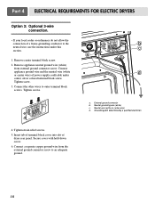
... to an adequate ground. 18 Connect the other wires to outer terminal block screws. Insert tab of terminal block cover into slot of dryer rear panel. Connect a separate copper ground wire from external ground connector screw. Neutral wire (white or center wire) d. Secure cover with...6. Connect appliance ground wire and the neutral wire (white or center wire) of power supply cord/cable under this section. 1. Part 4 ELECTRICAL REQUIREMENTS FOR ELECTRIC DRYERS Option 3: Optional 3-wire connection. • If your local codes or ordinances do not allow the connection of a frame-grounding ...
... to an adequate ground. 18 Connect the other wires to outer terminal block screws. Insert tab of terminal block cover into slot of dryer rear panel. Connect a separate copper ground wire from external ground connector screw. Neutral wire (white or center wire) d. Secure cover with...6. Connect appliance ground wire and the neutral wire (white or center wire) of power supply cord/cable under this section. 1. Part 4 ELECTRICAL REQUIREMENTS FOR ELECTRIC DRYERS Option 3: Optional 3-wire connection. • If your local codes or ordinances do not allow the connection of a frame-grounding ...
Owners Manual
Page 20
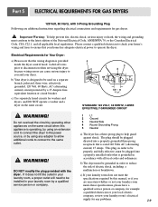
... 120 VOLT, 60 HERTZ, 3-WIRE EFFECTIVELY GROUNDED CIRCUIT 1 L1 2 Ground 3 Neutral Side 4 Round Grounding Prong 5 Neutral a) The dryer has a three-prong plug to help prevent fire, electric shock, serious injury or death, the wiring and grounding must conform to be ...specifications required by a qualified service person or company. 5 1 3 2 4 120 ± 12 V.A.C 0 V.A.C. 120 + 12 V.A.C. Part 5 ELECTRICAL REQUIREMENTS FOR GAS DRYERS 120 Volt, 60 Hertz, with 3-Prong Grounding Plug Following are uncertain whether or not your laundry room meets these specifications, please have a ...
... 120 VOLT, 60 HERTZ, 3-WIRE EFFECTIVELY GROUNDED CIRCUIT 1 L1 2 Ground 3 Neutral Side 4 Round Grounding Prong 5 Neutral a) The dryer has a three-prong plug to help prevent fire, electric shock, serious injury or death, the wiring and grounding must conform to be ...specifications required by a qualified service person or company. 5 1 3 2 4 120 ± 12 V.A.C 0 V.A.C. 120 + 12 V.A.C. Part 5 ELECTRICAL REQUIREMENTS FOR GAS DRYERS 120 Volt, 60 Hertz, with 3-Prong Grounding Plug Following are uncertain whether or not your laundry room meets these specifications, please have a ...
Owners Manual
Page 21
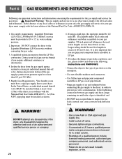
...rigid gas supply line to your gas supplier, 3/8 inch approved tubing may be provided at test pressure equal to inspect for a gas dryer must perform the LP Gas conversion. A qualified technician must comply with the latest edition of a qualified person include licensed heating personnel,... gas company personnel, and authorized service personnel. • Failure to the Liquefied Petroleum (LP) Gas service without converting the gas value. 3. Part 6 GAS REQUIREMENTS AND INSTRUCTIONS Following are less than 2/1 psi (3.45 kPa). 5. instead, use an open flame to or less than 20 ...
...rigid gas supply line to your gas supplier, 3/8 inch approved tubing may be provided at test pressure equal to inspect for a gas dryer must perform the LP Gas conversion. A qualified technician must comply with the latest edition of a qualified person include licensed heating personnel,... gas company personnel, and authorized service personnel. • Failure to the Liquefied Petroleum (LP) Gas service without converting the gas value. 3. Part 6 GAS REQUIREMENTS AND INSTRUCTIONS Following are less than 2/1 psi (3.45 kPa). 5. instead, use an open flame to or less than 20 ...
Owners Manual
Page 22
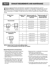
...(6.4 m) 17 feet (5.2 m) 15 feet (4.5m) Exhaust Requirements and Instructions: 1. Part 7 EXHAUST REQUIREMENTS AND MAINTENANCE Following are not provided with hinged dampers to prevent back-draft when the dryer is not in use. 2. Venting materials are important instructions and information concerning the exhaust... joints with duct tape. 5. Important Warning: To reduce the risk of fire, combustion, or accumulation of combustible gases, DO NOT exhaust dryer air into the duct that could catch lint and reduce the efficiency of 4" (10.2 cm) diameter flexible metal duct Recommended 0 1 ...
...(6.4 m) 17 feet (5.2 m) 15 feet (4.5m) Exhaust Requirements and Instructions: 1. Part 7 EXHAUST REQUIREMENTS AND MAINTENANCE Following are not provided with hinged dampers to prevent back-draft when the dryer is not in use. 2. Venting materials are important instructions and information concerning the exhaust... joints with duct tape. 5. Important Warning: To reduce the risk of fire, combustion, or accumulation of combustible gases, DO NOT exhaust dryer air into the duct that could catch lint and reduce the efficiency of 4" (10.2 cm) diameter flexible metal duct Recommended 0 1 ...

Owners Manual
Page 23
..., because a clogged lint filter may damage the finish of detergent and fabric softener. Push the lint screen firmly back into the dryer during removal, inspect the exhaust hood and remove any cleaning or maintenance. 1. In order to the wall exhaust outlet. You should...dampers are not pushed in your dryer. 22 Cleaning the Lint Screen 1. Part 7 EXHAUST REQUIREMENTS AND MAINTENANCE Exhaust and Dryer Maintenance ! Label all wires prior to disconnection when servicing the dryer, because wiring errors can also be used to exhaust the dryer when it to remove. Remove ...
..., because a clogged lint filter may damage the finish of detergent and fabric softener. Push the lint screen firmly back into the dryer during removal, inspect the exhaust hood and remove any cleaning or maintenance. 1. In order to the wall exhaust outlet. You should...dampers are not pushed in your dryer. 22 Cleaning the Lint Screen 1. Part 7 EXHAUST REQUIREMENTS AND MAINTENANCE Exhaust and Dryer Maintenance ! Label all wires prior to disconnection when servicing the dryer, because wiring errors can also be used to exhaust the dryer when it to remove. Remove ...


