
Service Manual
Page 4
... 7 GAS VALVE TEST - SPECIFICATIONS ...4 2. FEATURES AND BENEFITS ...5 3. COMPONENT TESTING INFORMATION 10 6. MEASURE WITH POWER OFF 18 9-3. WIRING DIAGRAM ...15 9. TEST 3 MOTOR TEST 19 9-4. TEST 4 MOISTURE SENSOR 20 9-5. CONTENTS 1. TEST 5 DOOR SWITCH TEST 21 9-6. REPLACEMENT PARTS LIST 36 3 COLUMBUS DRYER CYCLE PROCESS 9 5. DIAGNOSTIC TEST ...16 9-1. CHANGE GAS SETTING (NATURAL GAS, PROPANE GAS...
... 7 GAS VALVE TEST - SPECIFICATIONS ...4 2. FEATURES AND BENEFITS ...5 3. COMPONENT TESTING INFORMATION 10 6. MEASURE WITH POWER OFF 18 9-3. WIRING DIAGRAM ...15 9. TEST 3 MOTOR TEST 19 9-4. TEST 4 MOISTURE SENSOR 20 9-5. CONTENTS 1. TEST 5 DOOR SWITCH TEST 21 9-6. REPLACEMENT PARTS LIST 36 3 COLUMBUS DRYER CYCLE PROCESS 9 5. DIAGNOSTIC TEST ...16 9-1. CHANGE GAS SETTING (NATURAL GAS, PROPANE GAS...
Service Manual
Page 5
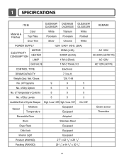
... 5 5 5 No. of Programs 9 9 5 No. Weight (lbs): Net / Gross 126 / 144 No. of Cycle Beeper High / Low / Off High / Low / Off On / Off Sensor Moisture Temperature Equipped Equipped Electro sensor Thermistor Reversible Door Adopted Drum Stainless Steel Dryer Rack Equipped Child lock Equipped Interior Light Equipped Product (WXHXD) Packing (WXHXD) 27" x 42 3/4" x 28...
... 5 5 5 No. of Programs 9 9 5 No. Weight (lbs): Net / Gross 126 / 144 No. of Cycle Beeper High / Low / Off High / Low / Off On / Off Sensor Moisture Temperature Equipped Equipped Electro sensor Thermistor Reversible Door Adopted Drum Stainless Steel Dryer Rack Equipped Child lock Equipped Interior Light Equipped Product (WXHXD) Packing (WXHXD) 27" x 42 3/4" x 28...
Service Manual
Page 17
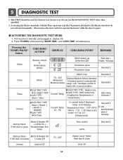
Unit must be used for Factory test /Service test. Displays Moisture Sensor Operation: If moisture sensor is contacted with the Door open may trip the Thermostat attached to the Heater, therefore do not activate it manually. (Do not press ... "POWER" while pressing "MORE TIME", and "LESS TIME" simultaneously. Pressing the "START/PAUSE" button CHECKING ACTION DISPLAY CHECKING POINT REMARK None Electric control & Temperature sensor Won't power up Defective LED Thermistor open ) ACTIVATING THE DIAGNOSTIC TEST MODE 1. Auto Off 16 This TEST should be in Standby (unit plugged in, display...
Unit must be used for Factory test /Service test. Displays Moisture Sensor Operation: If moisture sensor is contacted with the Door open may trip the Thermostat attached to the Heater, therefore do not activate it manually. (Do not press ... "POWER" while pressing "MORE TIME", and "LESS TIME" simultaneously. Pressing the "START/PAUSE" button CHECKING ACTION DISPLAY CHECKING POINT REMARK None Electric control & Temperature sensor Won't power up Defective LED Thermistor open ) ACTIVATING THE DIAGNOSTIC TEST MODE 1. Auto Off 16 This TEST should be in Standby (unit plugged in, display...

Service Manual
Page 21
...% 40% ~ 20% Display Value Voltage(DC) (between 6Pin terminal 50 ~ 130 2.5V 100 ~ 20 2.0V ~ 4.0V ) Remark Weight after removing from the Controller. Test 4 Moisture sensor Caution Before measuring resistance, be sure to Controller. YES • Replace Control and Check. Normal Condition Table 2. Damping cloth When contacting cloth to Electro load: 1.
...% 40% ~ 20% Display Value Voltage(DC) (between 6Pin terminal 50 ~ 130 2.5V 100 ~ 20 2.0V ~ 4.0V ) Remark Weight after removing from the Controller. Test 4 Moisture sensor Caution Before measuring resistance, be sure to Controller. YES • Replace Control and Check. Normal Condition Table 2. Damping cloth When contacting cloth to Electro load: 1.
Service Manual
Page 29
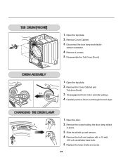
... remove Drum out through front of dryer. 1. Open the door. 2. Slide the shield up and remove. 4. Remove Cover Cabinet. 3. Disconnect the door lamp and electro sensor connector. 4. Remove the Cover Cabinet and Tub drum [front]. -2 3. Open the top plate. -1 2. Replace the lamp shield and screw. 28 Disengage belt from motor and...
... remove Drum out through front of dryer. 1. Open the door. 2. Slide the shield up and remove. 4. Remove Cover Cabinet. 3. Disconnect the door lamp and electro sensor connector. 4. Remove the Cover Cabinet and Tub drum [front]. -2 3. Open the top plate. -1 2. Replace the lamp shield and screw. 28 Disengage belt from motor and...
Service Manual
Page 31
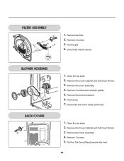
Remove the Drum assembly. 4. Remove the bolt and washer. 6. Remove the Cover Cabinet and Tub Drum [Front]. 3. Remove 3 screws. 3. Remove the Cover Cabinet and Tub Drum [Front]. 3. Remove the filter. 2. Disconnect electro sensor. 1. Remove the Drum assembly. 4. Open the top plate. 2. Open the top plate. 2. Disconnect the motor clamp and motor. 1. Remove 7 screws. 5. Pull the fan. 7. Pull the grill. 4. 1. Remove 2 screws and cover(Air guide). 5. Pull the Tub Drum [Rear] towards the front. 30
Remove the Drum assembly. 4. Remove the bolt and washer. 6. Remove the Cover Cabinet and Tub Drum [Front]. 3. Remove 3 screws. 3. Remove the Cover Cabinet and Tub Drum [Front]. 3. Remove the filter. 2. Disconnect electro sensor. 1. Remove the Drum assembly. 4. Open the top plate. 2. Open the top plate. 2. Disconnect the motor clamp and motor. 1. Remove 7 screws. 5. Pull the fan. 7. Pull the grill. 4. 1. Remove 2 screws and cover(Air guide). 5. Pull the Tub Drum [Rear] towards the front. 30


