
Service Manual
Page 4
......5 3. TEST 2 THERMISTOR TEST --- TEST 5 DOOR SWITCH TEST 21 9-6. REPLACEMENT PARTS LIST 36 3 WIRING DIAGRAM ...15 9. TEST 3 MOTOR TEST 19 9-4. EXPLODED VIEW ...32 12-1. DIAGNOSTIC TEST ...16 9-1. OUT ...14 8. TEST 1 120VAC ELECTRICAL SUPPLY 17 9-2. GAS TYPE 23...CYCLE PROCESS 9 5. TEST 7 GAS VALVE TEST - DRUM & MOTOR ASSEMBLY : ELECTRIC TYPE 34 12-3-2. TEST 6 HEATER SWITCH TEST - ELECTRIC TYPE 22 9-7. SPECIFICATIONS ...4 2. COMPONENT TESTING INFORMATION 10 6. DISASSEMBLY INSTRUCTIONS 26 12. MOTOR DIAGRAM AND SCHEMATIC 13 7. TEST 4 MOISTURE SENSOR 20 9-5.
......5 3. TEST 2 THERMISTOR TEST --- TEST 5 DOOR SWITCH TEST 21 9-6. REPLACEMENT PARTS LIST 36 3 WIRING DIAGRAM ...15 9. TEST 3 MOTOR TEST 19 9-4. EXPLODED VIEW ...32 12-1. DIAGNOSTIC TEST ...16 9-1. OUT ...14 8. TEST 1 120VAC ELECTRICAL SUPPLY 17 9-2. GAS TYPE 23...CYCLE PROCESS 9 5. TEST 7 GAS VALVE TEST - DRUM & MOTOR ASSEMBLY : ELECTRIC TYPE 34 12-3-2. TEST 6 HEATER SWITCH TEST - ELECTRIC TYPE 22 9-7. SPECIFICATIONS ...4 2. COMPONENT TESTING INFORMATION 10 6. DISASSEMBLY INSTRUCTIONS 26 12. MOTOR DIAGRAM AND SCHEMATIC 13 7. TEST 4 MOISTURE SENSOR 20 9-5.
Service Manual
Page 5
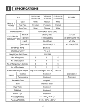
... REMARK Material & Finishes Color Top Plate Door Trim White Porcelain Silver Titanium Porcelain Chrome White Painted White POWER SUPPLY 120V / 240V 60Hz (26A) ELECTRICITY CONSUMPTION MOTOR HEATER LAMP 250W (4.5A) 5400W (22.5A) 15W (125mA) AC 120V AC 240V ( ELECTRIC TYPE) AC 120V GAS VALVE 13W (110mA) X 2 AC 120V ( GAS TYPE...
... REMARK Material & Finishes Color Top Plate Door Trim White Porcelain Silver Titanium Porcelain Chrome White Painted White POWER SUPPLY 120V / 240V 60Hz (26A) ELECTRICITY CONSUMPTION MOTOR HEATER LAMP 250W (4.5A) 5400W (22.5A) 15W (125mA) AC 120V AC 240V ( ELECTRIC TYPE) AC 120V GAS VALVE 13W (110mA) X 2 AC 120V ( GAS TYPE...

Service Manual
Page 10
...±5°C) Manual Dry ** Freshen Up (Medium High) - 20min Saturation (66±5°C) (5min) (47±5°C) 3Hr Air dry - - 30min Saturation No heater N/A N/A Load Motor Heater Off Time: 6min On Time: 10sec Temperature Control for each cycle * Sense dry : "Dry Level" is set by users. ** Manual dry : "Temperature control" is...
...±5°C) Manual Dry ** Freshen Up (Medium High) - 20min Saturation (66±5°C) (5min) (47±5°C) 3Hr Air dry - - 30min Saturation No heater N/A N/A Load Motor Heater Off Time: 6min On Time: 10sec Temperature Control for each cycle * Sense dry : "Dry Level" is set by users. ** Manual dry : "Temperature control" is...
Service Manual
Page 12
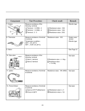
...°C) 58°F ~ 104F (10~40°C) Resistance value : 10Ω • Heater case Hi limit • Electric type • See Page 13 10. Component 7. Motor Test Procedure Measure resistance of the following terminal Valve 1 terminal Valve 2 terminal • Gas type Resistance value : > 1.5kg ~ Resistance value : > 1.5~2.5kg 11. Gas valve valve...
...°C) 58°F ~ 104F (10~40°C) Resistance value : 10Ω • Heater case Hi limit • Electric type • See Page 13 10. Component 7. Motor Test Procedure Measure resistance of the following terminal Valve 1 terminal Valve 2 terminal • Gas type Resistance value : > 1.5kg ~ Resistance value : > 1.5~2.5kg 11. Gas valve valve...
Service Manual
Page 14
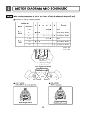
Contact On / Off by Centrifugal Switch STOP MODE (When Motor does not operate) RUN MODE (Motor operates) Centrifugal switch Centrifugal switch (Pull Drive forward) 13 6 MOTOR DIAGRAM AND SCHEMATIC NOTE When checking Component, be sure to turn Power off, then do voltage discharge sufficiently.
Contact On / Off by Centrifugal Switch STOP MODE (When Motor does not operate) RUN MODE (Motor operates) Centrifugal switch Centrifugal switch (Pull Drive forward) 13 6 MOTOR DIAGRAM AND SCHEMATIC NOTE When checking Component, be sure to turn Power off, then do voltage discharge sufficiently.
Service Manual
Page 17
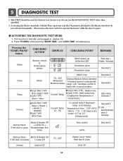
... switch to operate the heater while the door is open Thermistor close See test 1 Display : See page See test 2 Once Twice 3 times Motor Motor runs 70 ~ 237 Measured Moisture Value. Auto Off 16 9 DIAGNOSTIC TEST 1. This TEST should be in Standby (unit plugged in, display off... 2. Activating the Heater manually with damp cloth. Press "POWER" while pressing "MORE TIME", and "LESS TIME" simultaneously. ELECTRIC TYPE Motor + Heater 1 (1250W) GAS TYPE Motor + Valve Current Temp. ELECTRIC TYPE : Heater runs GAS TYPE : GAS Valve runs (Display the Temperature of Inside drum.) ELECTRIC TYPE...
... switch to operate the heater while the door is open Thermistor close See test 1 Display : See page See test 2 Once Twice 3 times Motor Motor runs 70 ~ 237 Measured Moisture Value. Auto Off 16 9 DIAGNOSTIC TEST 1. This TEST should be in Standby (unit plugged in, display off... 2. Activating the Heater manually with damp cloth. Press "POWER" while pressing "MORE TIME", and "LESS TIME" simultaneously. ELECTRIC TYPE Motor + Heater 1 (1250W) GAS TYPE Motor + Valve Current Temp. ELECTRIC TYPE : Heater runs GAS TYPE : GAS Valve runs (Display the Temperature of Inside drum.) ELECTRIC TYPE...
Service Manual
Page 20
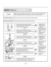
... then measure resistance. " (Brown wire)? " (Yellow wire)? NO Measure while door is closed . NO YES Does Idle Switch attached to Motor Bracket operate Level by drum belt? YES Measure while door is closed . No Heater will not rotate; " (White wire) and "BL2-...BL2- NO Is resistance below 3Ω between Connector "BL2- Test 3 Motor test Caution Before measuring resistance, be sure to turn Power off from • Motor Pulley. • Replace Idler Switch. • Check Motor.(Refer to 'Motor Diagram & Check') • Check if Control Connector is normal.) Is ...
... then measure resistance. " (Brown wire)? " (Yellow wire)? NO Measure while door is closed . NO YES Does Idle Switch attached to Motor Bracket operate Level by drum belt? YES Measure while door is closed . No Heater will not rotate; " (White wire) and "BL2-...BL2- NO Is resistance below 3Ω between Connector "BL2- Test 3 Motor test Caution Before measuring resistance, be sure to turn Power off from • Motor Pulley. • Replace Idler Switch. • Check Motor.(Refer to 'Motor Diagram & Check') • Check if Control Connector is normal.) Is ...
Service Manual
Page 22
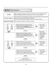
...below 250Ω between "BL2- Display will not operate. " (Yellow wire) and "WH3- Check if resistance is not sensed. (Drum motor will flash at 0.5 second intervals.) Measurement Condition After turning Dryer Power Off, measure resistance. Check if resistance is closed . " (White wire...) and "RD3- YES • Door switch Check (Refer to Component testing.) • Check Lamp. (When opening Door, Drum motor and Trouble Symptom Heater run continuously; NO • Door switch Check (Refer to Component testing.) Check Controller. YES • Door switch ...
...below 250Ω between "BL2- Display will not operate. " (Yellow wire) and "WH3- Check if resistance is not sensed. (Drum motor will flash at 0.5 second intervals.) Measurement Condition After turning Dryer Power Off, measure resistance. Check if resistance is closed . " (White wire...) and "RD3- YES • Door switch Check (Refer to Component testing.) • Check Lamp. (When opening Door, Drum motor and Trouble Symptom Heater run continuously; NO • Door switch Check (Refer to Component testing.) Check Controller. YES • Door switch ...
Service Manual
Page 23
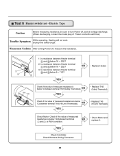
... if the value of measured resistance is below 1Ω between terminal NO and at RUN condition. • Check Motor and replace it. NO YES • Replace TH3 (HI-Limit Thermostat). Check Harness-linking Connector. 22 Measurement Condition After turning Power off , and do voltage ...
... if the value of measured resistance is below 1Ω between terminal NO and at RUN condition. • Check Motor and replace it. NO YES • Replace TH3 (HI-Limit Thermostat). Check Harness-linking Connector. 22 Measurement Condition After turning Power off , and do voltage ...
Service Manual
Page 29
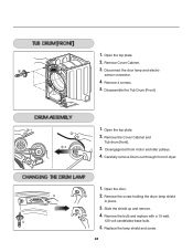
... up and remove. 4. Disconnect the door lamp and electro sensor connector. 4. Open the top plate. 2. Remove 4 screws. 5. Disassemble the Tub Drum [Front]. -1 1. Disengage belt from motor and idler pulleys. 4. 1. Open the top plate. -1 2. Open the door. 2. Remove the bulb and replace with a 15 watt, 120 volt candelabra-base bulb. 5. Replace the...
... up and remove. 4. Disconnect the door lamp and electro sensor connector. 4. Open the top plate. 2. Remove 4 screws. 5. Disassemble the Tub Drum [Front]. -1 1. Disengage belt from motor and idler pulleys. 4. 1. Open the top plate. -1 2. Open the door. 2. Remove the bulb and replace with a 15 watt, 120 volt candelabra-base bulb. 5. Replace the...
Service Manual
Page 31
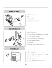
Remove the filter. 2. Remove the Cover Cabinet and Tub Drum [Front]. 3. Remove the Drum assembly. 4. Disconnect the motor clamp and motor. 1. Remove the Cover Cabinet and Tub Drum [Front]. 3. Remove 7 screws. 5. Pull the grill. 4. Disconnect electro sensor. 1. Remove 2 screws and cover(Air guide). 5. Pull the Tub Drum [Rear] towards the front. 30 Open the top plate. 2. Open the top plate. 2. Remove the bolt and washer. 6. Remove the Drum assembly. 4. Remove 3 screws. 3. Pull the fan. 7. 1.
Remove the filter. 2. Remove the Cover Cabinet and Tub Drum [Front]. 3. Remove the Drum assembly. 4. Disconnect the motor clamp and motor. 1. Remove the Cover Cabinet and Tub Drum [Front]. 3. Remove 7 screws. 5. Pull the grill. 4. Disconnect electro sensor. 1. Remove 2 screws and cover(Air guide). 5. Pull the Tub Drum [Rear] towards the front. 30 Open the top plate. 2. Open the top plate. 2. Remove the bolt and washer. 6. Remove the Drum assembly. 4. Remove 3 screws. 3. Pull the fan. 7. 1.
Service Manual
Page 35
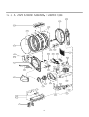
Drum & Motor Assembly : Electric Type F200 K400 K120 K140 K100 K130 K222 K221 K210 K240 K230 K350 F130 F110 F120 K250 K251 K330 K320 K340 K250 K251 K360 K550 K560 K310 K620 K610 F140 K515 K510 K540 K520 K640 K600 K530 K650 K651 34 12-3-1.
Drum & Motor Assembly : Electric Type F200 K400 K120 K140 K100 K130 K222 K221 K210 K240 K230 K350 F130 F110 F120 K250 K251 K330 K320 K340 K250 K251 K360 K550 K560 K310 K620 K610 F140 K515 K510 K540 K520 K640 K600 K530 K650 K651 34 12-3-1.
Parts Diagram
Page 4
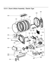
Drum & Motor Assembly : Electric Type K120 K100 K140 F200 K400 K130 K221 K230 K210 K350 K240 F140 F130 F110 F120 K250 K251 K330 K320 K340 K250 K251 K360 K550 K560 K310 K620 K610 K510 K520 K640 K540 K600 K530 K650 K651 12-3-1.
Drum & Motor Assembly : Electric Type K120 K100 K140 F200 K400 K130 K221 K230 K210 K350 K240 F140 F130 F110 F120 K250 K251 K330 K320 K340 K250 K251 K360 K550 K560 K310 K620 K610 K510 K520 K640 K540 K600 K530 K650 K651 12-3-1.

