
Owner's Manual
Page 13
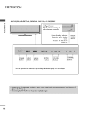
... 42/50PJ350, 42/50PJ340, 50PK340, 50PK350, 42/50PJ350C Intelligent Sensor Adjusts picture according to any impact.It may break, causing possible injury from fragments of glass, or the TV may be damaged. 12 The floor or the product may fall. The LED is off while the TV remains on the glass stand or...
... 42/50PJ350, 42/50PJ340, 50PK340, 50PK350, 42/50PJ350C Intelligent Sensor Adjusts picture according to any impact.It may break, causing possible injury from fragments of glass, or the TV may be damaged. 12 The floor or the product may fall. The LED is off while the TV remains on the glass stand or...
Owner's Manual
Page 17
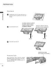
... protection cover over the hole for the stand. Press the PROTECTION COVER into the TV until you hear it click. 16 PROTECTION COVER (Fix a Guide to protect the screen from damage. 2 Loose the bolts from TV. (42/50PJ250, 50PK250, 42/50PJ340, 42/50PJ350, 50PK350, 50PK340, 50PK540, 42/50PJ550,... 50PK550, 42/50PJ350C, 50PK550C) (60PK250, 60PK540, 60PK550, 60PK280, 60PK290, 60PK550C) 3 Detach the stand from TV.
... protection cover over the hole for the stand. Press the PROTECTION COVER into the TV until you hear it click. 16 PROTECTION COVER (Fix a Guide to protect the screen from damage. 2 Loose the bolts from TV. (42/50PJ250, 50PK250, 42/50PJ340, 42/50PJ350, 50PK350, 50PK340, 50PK540, 42/50PJ550,... 50PK550, 42/50PJ350C, 50PK550C) (60PK250, 60PK540, 60PK550, 60PK280, 60PK290, 60PK550C) 3 Detach the stand from TV.
Owner's Manual
Page 110
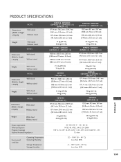
...stand Without stand Weight With stand Without stand MODEL Dimensions (Width x Height x Depth) With stand Without stand Weight With stand Without stand MODEL Dimensions (Width x Height x Depth) With stand Without stand Weight With stand Without stand MODEL Dimensions (Width x Height x Depth) With stand Without stand Weight With stand Without stand...(50PJ350-UB, 50PJ350C-UB) 1171.4 mm x 781.8 mm x 309.7 mm (46.1inches x 30.7 inch x 12.1 inch) 1171.4 mm x 720.9 mm x 55.3 mm (46.1inches x 28.3 inch x 2.1 inch) 30kg (66.1 lb) 27.6 kg (60.8 lb) 50PJ340 (50PJ340-UB, 50PJ340-UC, 50PJ340-...
...stand Without stand Weight With stand Without stand MODEL Dimensions (Width x Height x Depth) With stand Without stand Weight With stand Without stand MODEL Dimensions (Width x Height x Depth) With stand Without stand Weight With stand Without stand MODEL Dimensions (Width x Height x Depth) With stand Without stand Weight With stand Without stand...(50PJ350-UB, 50PJ350C-UB) 1171.4 mm x 781.8 mm x 309.7 mm (46.1inches x 30.7 inch x 12.1 inch) 1171.4 mm x 720.9 mm x 55.3 mm (46.1inches x 28.3 inch x 2.1 inch) 30kg (66.1 lb) 27.6 kg (60.8 lb) 50PJ340 (50PJ340-UB, 50PJ340-UC, 50PJ340-...
Training Manual
Page 13
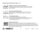
... default factory setting complies with the Energy Star requirements and is three preset picture and audio settings. Draws less than 1 Watt in stand by. 13 July 2010 50PJ350 Plasma 50PJ350 Logo Familiarization Page 3 of the human voice frequency range to provide high-quality dialogue when background noise swells. Less energy means you pay...
... default factory setting complies with the Energy Star requirements and is three preset picture and audio settings. Draws less than 1 Watt in stand by. 13 July 2010 50PJ350 Plasma 50PJ350 Logo Familiarization Page 3 of the human voice frequency range to provide high-quality dialogue when background noise swells. Less energy means you pay...
Training Manual
Page 17
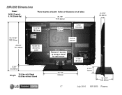
50PJ350 Dimensions Power: 340W (Typical) 0.1W (Stand-By) There must be at least 4 inches of Clearance on all sides 46-1/8" 1170.94mm 15-3/16" 385.8mm 15-3/4" 400mm 5-1/4" 133.6mm 2-3/16" 55.88mm 30-13/16" 782.32mm 28-3/8" 721.36mm Model No. Label 2-3/8" 60.96mm Weight: 78.5 lbs with Stand 60.8 lbs without Stand 15-3/4" 400mm Remove 4 screws to remove stand for wall mount 20-7/8" 530mm 17 7-3/8" 187.2mm 2-3/4" 70mm 12-3/16" 309.88mm July 2010 50PJ350 Plasma Serial No.
50PJ350 Dimensions Power: 340W (Typical) 0.1W (Stand-By) There must be at least 4 inches of Clearance on all sides 46-1/8" 1170.94mm 15-3/16" 385.8mm 15-3/4" 400mm 5-1/4" 133.6mm 2-3/16" 55.88mm 30-13/16" 782.32mm 28-3/8" 721.36mm Model No. Label 2-3/8" 60.96mm Weight: 78.5 lbs with Stand 60.8 lbs without Stand 15-3/4" 400mm Remove 4 screws to remove stand for wall mount 20-7/8" 530mm 17 7-3/8" 187.2mm 2-3/4" 70mm 12-3/16" 309.88mm July 2010 50PJ350 Plasma Serial No.
Training Manual
Page 19
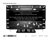
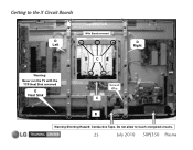
Improper type can damage the front. 19 July 2010 50PJ350 Plasma Removing the Back Cover To remove the back cover, remove the 32 screws Indicated by the arrows. (The Stand does not need to be removed). PAY CLOSE ATTENTION TO THE TYPE, SIZE AND LENGTH Of the screws when replacing the back cover.
Improper type can damage the front. 19 July 2010 50PJ350 Plasma Removing the Back Cover To remove the back cover, remove the 32 screws Indicated by the arrows. (The Stand does not need to be removed). PAY CLOSE ATTENTION TO THE TYPE, SIZE AND LENGTH Of the screws when replacing the back cover.
Training Manual
Page 22
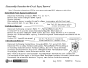
... P201~P203: Disconnect P212 by lifting up on the locking mechanism and pull the ribbon cable out. Remove the Y-SUS board. Lift up on board stand-offs that act as well. Collar Note: Y-SUS, Z-SUS and Y-Drive boards are mounted on the locking mechanism and pull the ribbon cable out. ... Label. The board must be sure to readjust the Va/Vs voltages in place. They may make the board stick when removing. 22 July 2010 50PJ350 Plasma When replacing, be lifted slightly to the Lower Y-Drive Disconnect the following connectors: P812, P813 and SC101. Note: The Y-SUS does not come ...
... P201~P203: Disconnect P212 by lifting up on the locking mechanism and pull the ribbon cable out. Remove the Y-SUS board. Lift up on board stand-offs that act as well. Collar Note: Y-SUS, Z-SUS and Y-Drive boards are mounted on the locking mechanism and pull the ribbon cable out. ... Label. The board must be sure to readjust the Va/Vs voltages in place. They may make the board stick when removing. 22 July 2010 50PJ350 Plasma When replacing, be lifted slightly to the Lower Y-Drive Disconnect the following connectors: P812, P813 and SC101. Note: The Y-SUS does not come ...
Training Manual
Page 23
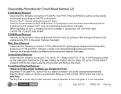
... panel. Front IR and Key Pad Removal FRONT IR/INTELLIGENT SENSOR and POWER BUTTON: Disconnect P100 and P101. Lift up slightly to clear the screw stand-offs and pull the Z-SUS to the left. Disassembly Procedure for Circuit Board Removal (2) Z-SUS Board Removal Disconnect the following connectors: P1 and P2, then... the locking tabs) and pull out, P704 and P801. Remove 1 screw in the decorative plastic piece and remove. It is not removable. 23 July 2010 50PJ350 Plasma
... panel. Front IR and Key Pad Removal FRONT IR/INTELLIGENT SENSOR and POWER BUTTON: Disconnect P100 and P101. Lift up slightly to clear the screw stand-offs and pull the Z-SUS to the left. Disassembly Procedure for Circuit Board Removal (2) Z-SUS Board Removal Disconnect the following connectors: P1 and P2, then... the locking tabs) and pull out, P704 and P801. Remove 1 screw in the decorative plastic piece and remove. It is not removable. 23 July 2010 50PJ350 Plasma
Training Manual
Page 24
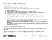
... to the left to the board. X Drive Circuit Board Removal Continued Make sure AC is removed. Make sure to flex the panel glass. c) Remove the Stand Metal Support Bracket (5 Screws) 2 Plastic tap thread and 3 Metal thread. Remove the (3 Left or Right X) or (5 Center X) screws holding the Heat Sink... so as not to use at least two people for this heat sink removed). Recheck Va / Vs / VScan / -VY / Z-Drive. 24 July 2010 50PJ350 Plasma Note: There are 5 Screws per/brace, 2 Plastic tap thread and 3 Metal thread. (Note, the right brace has a Grounding wire from the defective...
... to the left to the board. X Drive Circuit Board Removal Continued Make sure AC is removed. Make sure to flex the panel glass. c) Remove the Stand Metal Support Bracket (5 Screws) 2 Plastic tap thread and 3 Metal thread. Remove the (3 Left or Right X) or (5 Center X) screws holding the Heat Sink... so as not to use at least two people for this heat sink removed). Recheck Va / Vs / VScan / -VY / Z-Drive. 24 July 2010 50PJ350 Plasma Note: There are 5 Screws per/brace, 2 Plastic tap thread and 3 Metal thread. (Note, the right brace has a Grounding wire from the defective...
Training Manual
Page 25
Do not allow to the X Circuit Boards D Left With Stand removed C D Right Warning: Never run the TV with the TCP Heat Sink removed E Heat Sink Ground Wire C B Warning Shorting Hazard: Conductive Tape. Getting to touch energized circuits. 25 July 2010 50PJ350 Plasma
Do not allow to the X Circuit Boards D Left With Stand removed C D Right Warning: Never run the TV with the TCP Heat Sink removed E Heat Sink Ground Wire C B Warning Shorting Hazard: Conductive Tape. Getting to touch energized circuits. 25 July 2010 50PJ350 Plasma
Training Manual
Page 30
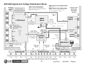
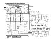
50PJ350 Signal and Voltage Distribution Block Y Drive Upper FPCs 5VFG (5V) measured from Floating Ground 15VFG (15V) measured from Floating Ground SMPS TURN ON SEQUENCE... CONTROL Board P101 Error Com SMPS Turn On Commands RL_ON Vs 17V, +5V, AC Det Z-SUS Board P2 FPCs P101 M_On M5V, Va, Vs P102 Stand By: STB +5 Run: AC Det +5, 17V 16V / M5V Z Drive Control P1 Signals P3 Z-SUB P7 Board P202 FPCs P203 P205 P212 Y Drive Floating...P104 P105 P201 P202 P203 P204 P205 P206 P301 P302 P303 P304 P305 Display Panel Vertical Address (Colored Cell Address) 30 July 2010 50PJ350 Plasma
50PJ350 Signal and Voltage Distribution Block Y Drive Upper FPCs 5VFG (5V) measured from Floating Ground 15VFG (15V) measured from Floating Ground SMPS TURN ON SEQUENCE... CONTROL Board P101 Error Com SMPS Turn On Commands RL_ON Vs 17V, +5V, AC Det Z-SUS Board P2 FPCs P101 M_On M5V, Va, Vs P102 Stand By: STB +5 Run: AC Det +5, 17V 16V / M5V Z Drive Control P1 Signals P3 Z-SUB P7 Board P202 FPCs P203 P205 P212 Y Drive Floating...P104 P105 P201 P202 P203 P204 P205 P206 P301 P302 P303 P304 P305 Display Panel Vertical Address (Colored Cell Address) 30 July 2010 50PJ350 Plasma
Training Manual
Page 35
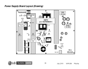
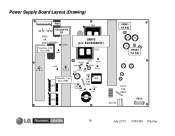
Power Supply Board Layout (Drawing) P812 VA TP VS TP F801 4A 250V Stand-By: 0.9V Run: 388V VS and VA TP ZD803 D805 T901 SMPS p/n: EAY60968701 T902 VR901 VS Adj VR502 VA Adj ZD302 D609 ZD401 D601 D307 ZD301 ZD303 D601 D303 ZD101 D305 Stand-By: 1.5V Run: 388V L601 D308 D309 D306 D302 F302 2.5A 250V T301 D103 D301 L602 F101 10A 250V SC101 P813 35 July 2010 50PJ350 Plasma
Power Supply Board Layout (Drawing) P812 VA TP VS TP F801 4A 250V Stand-By: 0.9V Run: 388V VS and VA TP ZD803 D805 T901 SMPS p/n: EAY60968701 T902 VR901 VS Adj VR502 VA Adj ZD302 D609 ZD401 D601 D307 ZD301 ZD303 D601 D303 ZD101 D305 Stand-By: 1.5V Run: 388V L601 D308 D309 D306 D302 F302 2.5A 250V T301 D103 D301 L602 F101 10A 250V SC101 P813 35 July 2010 50PJ350 Plasma
Training Manual
Page 38
...8 Center Va 3.3V 7 8 Va 7 X PWB Right 2 Front IR 4 Board Soft Touch Key Pad Remote Power Key Power Key 38 July 2010 50PJ350 Plasma If missing, set shuts off in Stand-By state. Det. 5V 5V 17V 6 2 If missing set will not turn on. Error Det. 3.3V Reg IC302 3.3VST 5 17V Audio IC801...Relay Det. On Microprocessor IC1 M_On 7 4 At point 3 TV is Energy Star Compliant. It is in 10 Sec. 6 6 RL On Not Used 5 6 M_On 7 AC Det. 50PJ350 POWER SUPPLY START UP SEQUENCE F302 In Stand-By Primary side is 1.5V In Run (Relay On) Primary side is 388V F801 POWER SUPPLY 7 AC In...
...8 Center Va 3.3V 7 8 Va 7 X PWB Right 2 Front IR 4 Board Soft Touch Key Pad Remote Power Key Power Key 38 July 2010 50PJ350 Plasma If missing, set shuts off in Stand-By state. Det. 5V 5V 17V 6 2 If missing set will not turn on. Error Det. 3.3V Reg IC302 3.3VST 5 17V Audio IC801...Relay Det. On Microprocessor IC1 M_On 7 4 At point 3 TV is Energy Star Compliant. It is in 10 Sec. 6 6 RL On Not Used 5 6 M_On 7 AC Det. 50PJ350 POWER SUPPLY START UP SEQUENCE F302 In Stand-By Primary side is 1.5V In Run (Relay On) Primary side is 388V F801 POWER SUPPLY 7 AC In...
Training Manual
Page 39
Power Supply Board Layout (Drawing) P812 VA TP VS TP F801 4A 250V Stand-By: 0.9V Run: 388V VS and VA TP ZD803 D805 T901 SMPS p/n: EAY60968701 T902 VR901 VS Adj VR502 VA Adj ZD302 D609 ZD401 D601 D307 ZD301 ZD303 D601 D303 ZD101 D305 Stand-By: 1.5V Run: 388V L601 D308 D309 D306 D302 F302 2.5A 250V T301 D103 D301 L602 F101 10A 250V SC101 P813 39 July 2010 50PJ350 Plasma
Power Supply Board Layout (Drawing) P812 VA TP VS TP F801 4A 250V Stand-By: 0.9V Run: 388V VS and VA TP ZD803 D805 T901 SMPS p/n: EAY60968701 T902 VR901 VS Adj VR502 VA Adj ZD302 D609 ZD401 D601 D307 ZD301 ZD303 D601 D303 ZD101 D305 Stand-By: 1.5V Run: 388V L601 D308 D309 D306 D302 F302 2.5A 250V T301 D103 D301 L602 F101 10A 250V SC101 P813 39 July 2010 50PJ350 Plasma
Training Manual
Page 64
... 0.95V 1.01V 0.62V 1.08V 0.06V Gnd Diode 1.02V 1.14V 1.14V 1.14V 1.14V 1.14V 1.14V 1.14V 1.14V 1.14V 1.14V 1.14V 1.14V 1.14V Gnd There are No Stand By Voltages on this Connector c Diode Mode Readings taken with all connectors Disconnected. DVM in Diode Mode. 64 July 2010...
... 0.95V 1.01V 0.62V 1.08V 0.06V Gnd Diode 1.02V 1.14V 1.14V 1.14V 1.14V 1.14V 1.14V 1.14V 1.14V 1.14V 1.14V 1.14V 1.14V 1.14V Gnd There are No Stand By Voltages on this Connector c Diode Mode Readings taken with all connectors Disconnected. DVM in Diode Mode. 64 July 2010...
Training Manual
Page 73
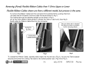
... Up Here Be sure ribbon tab is released By lifting the ribbon up the entire Ribbon Cable gently to the locked position see ( Fig 3 ), be standing straight up as shown in Fig 1). Locking tab in Fig 2. Lift up slightly, before removing ribbon. The locking tab must be sure the Tab is... the Ribbon Cable, carefully slide it forward ( lift from the back and tilt it back into the slot see ( Fig 2 then Fig 1). 73 July 2010 50PJ350 Plasma
... Up Here Be sure ribbon tab is released By lifting the ribbon up the entire Ribbon Cable gently to the locked position see ( Fig 3 ), be standing straight up as shown in Fig 1). Locking tab in Fig 2. Lift up slightly, before removing ribbon. The locking tab must be sure the Tab is... the Ribbon Cable, carefully slide it forward ( lift from the back and tilt it back into the slot see ( Fig 2 then Fig 1). 73 July 2010 50PJ350 Plasma
Training Manual
Page 75
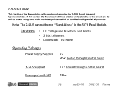
... Operating Voltages Power Supply Supplied VS M5V Routed through Control Board Y-SUS Supplied Developed on Z-SUS 16V Routed through Control Board Z Bias 75 July 2010 50PJ350 Plasma Note: The Z-SUS can not be able to locate voltage and diode mode test points needed for troubleshooting and all alignments. Z-SUS SECTION This... Presentation will have a better understanding of this section the Technician will cover troubleshooting the Z-SUS Board Assembly. Upon completion of the circuit and be run "Stand-Alone" in the 50T1 Panel Models.
... Operating Voltages Power Supply Supplied VS M5V Routed through Control Board Y-SUS Supplied Developed on Z-SUS 16V Routed through Control Board Z Bias 75 July 2010 50PJ350 Plasma Note: The Z-SUS can not be able to locate voltage and diode mode test points needed for troubleshooting and all alignments. Z-SUS SECTION This... Presentation will have a better understanding of this section the Technician will cover troubleshooting the Z-SUS Board Assembly. Upon completion of the circuit and be run "Stand-Alone" in the 50T1 Panel Models.
Training Manual
Page 81
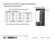
Connector P2 to Y-SUS P211 Voltages and Diode Checks Voltage and Diode Mode Measurements P2 Location: Top Left There are no Stand-By voltages on this connector P2 "Z-SUS" to "Y-SUS" P211 Pin Label Run 1~2 Gnd Gnd 3 n/c n/c 4~5 +Vs *206V 6 n/c n/c 7~11 ER_COM 98V~102V Diode Check Gnd n/c Open n/c Open Pin 1 * Note: This voltage will vary in Diode Mode. 81 July 2010 50PJ350 Plasma DVM in accordance with Panel Label Diode Mode Readings taken with all connectors Disconnected.
Connector P2 to Y-SUS P211 Voltages and Diode Checks Voltage and Diode Mode Measurements P2 Location: Top Left There are no Stand-By voltages on this connector P2 "Z-SUS" to "Y-SUS" P211 Pin Label Run 1~2 Gnd Gnd 3 n/c n/c 4~5 +Vs *206V 6 n/c n/c 7~11 ER_COM 98V~102V Diode Check Gnd n/c Open n/c Open Pin 1 * Note: This voltage will vary in Diode Mode. 81 July 2010 50PJ350 Plasma DVM in accordance with Panel Label Diode Mode Readings taken with all connectors Disconnected.
Training Manual
Page 82
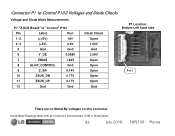
Connector P1 to Control P102 Voltages and Diode Checks Voltage and Diode Mode Measurements P1 "Z-SUS Board" to "Control" P101 Pin Label Run 1~2 (+15V) 16V 3~4 (+5V) 4.9V 5 Gnd Gnd 6 Y_OE 0.058V 7 ZBIAS 1.83V 8 SLOP_CONTROL Gnd 9 Z_ER 0.14V 10 ZSUS_DN 0.77V 11 ZSUS_UP 0.17V 12 Gnd Gnd Diode Check Open 1.52V Gnd 3.09V Open Open Open Open Open Gnd P1 Location: Bottom Left hand side Pin 1 There are no Stand-By voltages on this connector Diode Mode Readings taken with all connectors Disconnected. DVM in Diode Mode. 82 July 2010 50PJ350 Plasma
Connector P1 to Control P102 Voltages and Diode Checks Voltage and Diode Mode Measurements P1 "Z-SUS Board" to "Control" P101 Pin Label Run 1~2 (+15V) 16V 3~4 (+5V) 4.9V 5 Gnd Gnd 6 Y_OE 0.058V 7 ZBIAS 1.83V 8 SLOP_CONTROL Gnd 9 Z_ER 0.14V 10 ZSUS_DN 0.77V 11 ZSUS_UP 0.17V 12 Gnd Gnd Diode Check Open 1.52V Gnd 3.09V Open Open Open Open Open Gnd P1 Location: Bottom Left hand side Pin 1 There are no Stand-By voltages on this connector Diode Mode Readings taken with all connectors Disconnected. DVM in Diode Mode. 82 July 2010 50PJ350 Plasma
Training Manual
Page 91
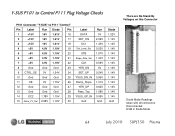
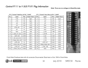
... I_SET_UP 0.24V 2.82V 26 I_Ramp_Slope_Opt1 1.01V 2.82V 28 I_Pass_Top 1.08V 2.82V 30 Gnd Gnd Gnd Diode Mode Readings taken with all connectors Disconnected. DVM in Stand-By mode P111 "Control" Odd Pins to P101 "Y-SUS" Pin Label Run Diode Check 1 +15V 16V Open 3 +15V 16V Open 5 +5V 4.9V 1.52V 7 +5V 4.9V... 2.83V 29 I_YSUS_UP_IN 0.06V 2.84V P111 "Control" Even Pins to Y-SUS P101 Plug Information Note: There are no voltages in Diode Mode. 91 July 2010 50PJ350 Plasma
... I_SET_UP 0.24V 2.82V 26 I_Ramp_Slope_Opt1 1.01V 2.82V 28 I_Pass_Top 1.08V 2.82V 30 Gnd Gnd Gnd Diode Mode Readings taken with all connectors Disconnected. DVM in Stand-By mode P111 "Control" Odd Pins to P101 "Y-SUS" Pin Label Run Diode Check 1 +15V 16V Open 3 +15V 16V Open 5 +5V 4.9V 1.52V 7 +5V 4.9V... 2.83V 29 I_YSUS_UP_IN 0.06V 2.84V P111 "Control" Even Pins to Y-SUS P101 Plug Information Note: There are no voltages in Diode Mode. 91 July 2010 50PJ350 Plasma


