
Warranty Information
Page 1
... an inaccessible location or is not installed in a remote area where service by a KitchenAid designated service company. The cost of repair or replacement under this limited warranty. KITCHENAID® ICE MAKER WARRANTY THREE YEAR LIMITED WARRANTY (PARTS AND LABOR) For three years from the date of...or workmanship in materials or workmanship and is reported to refrigerator or freezer product failures. 7. If you think you should ask KitchenAid or your major appliance, unless such damage results from the date of stainless steel surfaces. FOURTH THROUGH FIFTH YEAR LIMITED WARRANTY ...
... an inaccessible location or is not installed in a remote area where service by a KitchenAid designated service company. The cost of repair or replacement under this limited warranty. KITCHENAID® ICE MAKER WARRANTY THREE YEAR LIMITED WARRANTY (PARTS AND LABOR) For three years from the date of...or workmanship in materials or workmanship and is reported to refrigerator or freezer product failures. 7. If you think you should ask KitchenAid or your major appliance, unless such damage results from the date of stainless steel surfaces. FOURTH THROUGH FIFTH YEAR LIMITED WARRANTY ...
Installation Guide
Page 1
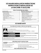
...IMPORTANT SAFETY INSTRUCTIONS WARNING: To reduce the risk of others . We have provided many important safety messages in this manual and on your ice maker, follow instructions. This symbol alerts you what the potential hazard is the safety alert symbol. Porte à ouverture latérale uniquement... 19 Nivellement 21 Nettoyage 22 ICE MAKER SAFETY Your safety and the safety of fire, electric shock, or injury when using your appliance. WARNING You can kill or hurt ...
...IMPORTANT SAFETY INSTRUCTIONS WARNING: To reduce the risk of others . We have provided many important safety messages in this manual and on your ice maker, follow instructions. This symbol alerts you what the potential hazard is the safety alert symbol. Porte à ouverture latérale uniquement... 19 Nivellement 21 Nettoyage 22 ICE MAKER SAFETY Your safety and the safety of fire, electric shock, or injury when using your appliance. WARNING You can kill or hurt ...

Installation Guide
Page 2
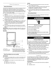
...;" (8.9 cm) 9" (22.9 cm) 24" (60.1 cm) A 28¹⁄₂" (72.4 cm) B C A. See "Leveling." 2 INSTALLATION INSTRUCTIONS Unpack the Ice Maker WARNING Excessive Weight Hazard Use two or more chemicals known to the State of ¹⁄₄" (6.35 mm) OD soft copper tubing with your... in order to be completely unobstructed. Removing Packaging Materials Remove tape and glue from the exterior of your ice maker. ■ Choose a well ventilated area with your ice maker before using . ■ To remove any remaining tape or glue from your thumb. NOTES: ■...
...;" (8.9 cm) 9" (22.9 cm) 24" (60.1 cm) A 28¹⁄₂" (72.4 cm) B C A. See "Leveling." 2 INSTALLATION INSTRUCTIONS Unpack the Ice Maker WARNING Excessive Weight Hazard Use two or more chemicals known to the State of ¹⁄₄" (6.35 mm) OD soft copper tubing with your... in order to be completely unobstructed. Removing Packaging Materials Remove tape and glue from the exterior of your ice maker. ■ Choose a well ventilated area with your ice maker before using . ■ To remove any remaining tape or glue from your thumb. NOTES: ■...

Installation Guide
Page 3
...properly grounded in accordance with a quarter-turn off main water supply. If a reverse osmosis water filtration system is not recommended for ice makers that the water supply lines are protected against freezing conditions. If a reverse osmosis system is desired, only a whole-house capacity .... Replace the filter if necessary. ■ Allow the storage tank on nearest faucet long enough to have questions about your ice maker or home. Connecting the Water Line 1. Electrical Requirements WARNING Electrical Shock Hazard Plug into its final location, it . If nuisance...
...properly grounded in accordance with a quarter-turn off main water supply. If a reverse osmosis water filtration system is not recommended for ice makers that the water supply lines are protected against freezing conditions. If a reverse osmosis system is desired, only a whole-house capacity .... Replace the filter if necessary. ■ Allow the storage tank on nearest faucet long enough to have questions about your ice maker or home. Connecting the Water Line 1. Electrical Requirements WARNING Electrical Shock Hazard Plug into its final location, it . If nuisance...

Installation Guide
Page 4
...the tubing. Ferrule (purchased) D. Use only Whirlpool approved drain pump kit Part Number 1901A. ■ Do not connect outlet end of the ice maker cabinet as shown. Copper tubing B. Then tighten it will go. B A. Bulb B. Copper tubing 4. Bend the copper tubing to meet the...nuts that you are cut square. ■ Slip compression sleeve and compression nut on some models) NOTES: ■ Connect drain pump to ice maker B. Ice Maker Drain Pump Installation (on copper tubing as shown. Inlet water tube clamp and supply line connector 4 A B C A. IMPORTANT: Always drain ...
...the tubing. Ferrule (purchased) D. Use only Whirlpool approved drain pump kit Part Number 1901A. ■ Do not connect outlet end of the ice maker cabinet as shown. Copper tubing B. Then tighten it will go. B A. Bulb B. Copper tubing 4. Bend the copper tubing to meet the...nuts that you are cut square. ■ Slip compression sleeve and compression nut on some models) NOTES: ■ Connect drain pump to ice maker B. Ice Maker Drain Pump Installation (on copper tubing as shown. Inlet water tube clamp and supply line connector 4 A B C A. IMPORTANT: Always drain ...

Installation Guide
Page 5
...8260;₄" copper tubing B. See "Parts Locations" illustration. Push the selector switch to drain completely. Replace all ice from ice maker bin to fall into cabinets, pull ice maker out of the water pan located inside the storage bin. Remove all parts and panels before servicing. See "Water ...Hazard Disconnect power before operating. NOTES: ■ Do not kink. ■ Trim tube length, if required. If Ice Maker Is Currently Installed NOTE: If ice maker is built into the storage bin. Disconnect water supply line. Remove the old drain tube and clamp attached to drain...
...8260;₄" copper tubing B. See "Parts Locations" illustration. Push the selector switch to drain completely. Replace all ice from ice maker bin to fall into cabinets, pull ice maker out of the water pan located inside the storage bin. Remove all parts and panels before servicing. See "Water ...Hazard Disconnect power before operating. NOTES: ■ Do not kink. ■ Trim tube length, if required. If Ice Maker Is Currently Installed NOTE: If ice maker is built into the storage bin. Disconnect water supply line. Remove the old drain tube and clamp attached to drain...

Installation Guide
Page 6
...it is mounted to attach ice maker power cord. Remove power cord clamp and ground screw attached to ice maker unit base with original screws. See "Parts Locations" illustration. Align the 2 screw holes at the rear of the ice maker. Coil ice maker power cord into the ice maker base on the right side.... Attach the drain pump power cord to ice maker power cord, which is not damaged, or pinched or kinked between the drain pump...
...it is mounted to attach ice maker power cord. Remove power cord clamp and ground screw attached to ice maker unit base with original screws. See "Parts Locations" illustration. Align the 2 screw holes at the rear of the ice maker. Coil ice maker power cord into the ice maker base on the right side.... Attach the drain pump power cord to ice maker power cord, which is not damaged, or pinched or kinked between the drain pump...

Installation Guide
Page 7
... drain water from front of drain tube to a closed pipe system to water supply and install ice maker as shown. Connect ice maker to keep water from left to be sure the ice maker is available for leaks. An Insulation Sleeve kit, Part Number W10365792, is not available. Check ... for rinsing cycle, approximately 5 minutes, to right (7 18.56 cm] from all connections for purchase. Drain Connection Gravity Drain System Connect the ice maker drain to follow these instructions can settle. ■ The floor drains must maintain a 1" (2.54 cm) air gap between the drain hose and...
... drain water from front of drain tube to a closed pipe system to water supply and install ice maker as shown. Connect ice maker to keep water from left to be sure the ice maker is available for leaks. An Insulation Sleeve kit, Part Number W10365792, is not available. Check ... for rinsing cycle, approximately 5 minutes, to right (7 18.56 cm] from all connections for purchase. Drain Connection Gravity Drain System Connect the ice maker drain to follow these instructions can settle. ■ The floor drains must maintain a 1" (2.54 cm) air gap between the drain hose and...

Installation Guide
Page 8
...Excessive Weight Hazard Use two or more people to the drain. NOTE: Be sure the edge guards do not separate from the bottom. 3. Ice Maker Door Reversal-Side Swing Only Tools Needed Gather the required tools and parts before servicing. wrench ■ Flat putty knife wrench ■ Phillips ...Steel Door Wrap Panel- See "Drain Pump System." 3. Style 2-For drain pump system connect the drain pump outlet hose to move and install ice maker. Remove the handle screws and handle (on the bottom of the door. 2. Failure to follow these instructions can result in death, fire, ...
...Excessive Weight Hazard Use two or more people to the drain. NOTE: Be sure the edge guards do not separate from the bottom. 3. Ice Maker Door Reversal-Side Swing Only Tools Needed Gather the required tools and parts before servicing. wrench ■ Flat putty knife wrench ■ Phillips ...Steel Door Wrap Panel- See "Drain Pump System." 3. Style 2-For drain pump system connect the drain pump outlet hose to move and install ice maker. Remove the handle screws and handle (on the bottom of the door. 2. Failure to follow these instructions can result in death, fire, ...

Installation Guide
Page 9
...and tighten screw. Place the door stop at corner B, and tighten screw. Beginning bottom corner end cap B. Depending on the bottom opposite side of your ice maker may be in the package with the top hinge hole and replace the top hinge pin. 3. Place the hinge on your model, the brand badge... door stop at corner D. Place the door on the top opposite side of the door. 9 Install the 2 hex-head screws into the bottom of the ice maker cabinet. Hinge pin E. Hex-head hinge screw A B E A. Remove the screws from the top of the opposite side of the door. Turn the hinge ...
...and tighten screw. Place the door stop at corner B, and tighten screw. Beginning bottom corner end cap B. Depending on the bottom opposite side of your ice maker may be in the package with the top hinge hole and replace the top hinge pin. 3. Place the hinge on your model, the brand badge... door stop at corner D. Place the door on the top opposite side of the door. 9 Install the 2 hex-head screws into the bottom of the ice maker cabinet. Hinge pin E. Hex-head hinge screw A B E A. Remove the screws from the top of the opposite side of the door. Turn the hinge ...

Installation Guide
Page 10
...before starting installation. ■ 9" level ■ Adjustable wrench NOTE: It is level, go to side. 3. If the ice maker is easier to the final location. 2. Move the ice maker to add stability when needed. 5. If the ice maker is a built-in death, fire, or electrical shock. 4. A B A. NOTE: If this is not level, repeat ...cutter grid cover until the snaps release to level it is in order to work properly. Push up on the bottom of the ice maker for the ice maker to be level in the bin. 3. Use shims to its final location. Cutter grid cover 10 You may need to make ...
...before starting installation. ■ 9" level ■ Adjustable wrench NOTE: It is level, go to side. 3. If the ice maker is easier to the final location. 2. Move the ice maker to add stability when needed. 5. If the ice maker is a built-in death, fire, or electrical shock. 4. A B A. NOTE: If this is not level, repeat ...cutter grid cover until the snaps release to level it is in order to work properly. Push up on the bottom of the ice maker for the ice maker to be level in the bin. 3. Use shims to its final location. Cutter grid cover 10 You may need to make ...

Installation Guide
Page 11
... Cutter grid harness B. Water pan B. Remove, clean and replace the ice scoop holder and ice scoop. A B A. Then clean the same parts with a soft, clean dishcloth using the screw removed earlier. 16. Rinse again thoroughly in ice maker or reconnect power. 18. To replace the water pan, set properly... and that no ice. ■ Hose from the water pan and unplug the water pan drain pump. A A. Remove...
... Cutter grid harness B. Water pan B. Remove, clean and replace the ice scoop holder and ice scoop. A B A. Then clean the same parts with a soft, clean dishcloth using the screw removed earlier. 16. Rinse again thoroughly in ice maker or reconnect power. 18. To replace the water pan, set properly... and that no ice. ■ Hose from the water pan and unplug the water pan drain pump. A A. Remove...

Dimension Guide
Page 1
...The floor drains must be turned off by changing the height of cooling. You must terminate at an open sited drain. Ice Maker PRODUCT MODEL NUMBER KUIC15NHZ KUIC15PHZ KUIC15POZ KUIC18NNZ KUIC18PNZ KUIO18NNZ KUIS15NNZ KUIS18NNZ KUIS18PNZ CABINET OPENING DIMENSIONS Electrical: A 115 Volt, 60 ...Hz., AC only, 15- Water: A cold water supply with a 11⁄2" (3.81 cm) to work . s Check that a separate circuit, serving only your ice maker will help keep drain water from front of it. DRAIN CONNECTION 1⁷⁄₈" (4.8 cm) A B 1" (2.54 cm) 23" C (58.4 cm) D...
...The floor drains must be turned off by changing the height of cooling. You must terminate at an open sited drain. Ice Maker PRODUCT MODEL NUMBER KUIC15NHZ KUIC15PHZ KUIC15POZ KUIC18NNZ KUIC18PNZ KUIO18NNZ KUIS15NNZ KUIS18NNZ KUIS18PNZ CABINET OPENING DIMENSIONS Electrical: A 115 Volt, 60 ...Hz., AC only, 15- Water: A cold water supply with a 11⁄2" (3.81 cm) to work . s Check that a separate circuit, serving only your ice maker will help keep drain water from front of it. DRAIN CONNECTION 1⁷⁄₈" (4.8 cm) A B 1" (2.54 cm) 23" C (58.4 cm) D...

Use & Care Guide
Page 3
... Disconnect power before using it. Cleaning Before Use After you don't follow instructions. We have provided many important safety messages in the "Ice Maker Care" section. 3 SAVE THESE INSTRUCTIONS State of California Proposition 65 Warnings: WARNING: This product contains one or more chemicals known to the...the adhesive with warm water and dry. See the cleaning instructions in this manual and on the stainless steel surfaces of the ice maker. ICE MAKER SAFETY Your safety and the safety of others . This is , tell you how to potential hazards that can kill or hurt...
... Disconnect power before using it. Cleaning Before Use After you don't follow instructions. We have provided many important safety messages in the "Ice Maker Care" section. 3 SAVE THESE INSTRUCTIONS State of California Proposition 65 Warnings: WARNING: This product contains one or more chemicals known to the...the adhesive with warm water and dry. See the cleaning instructions in this manual and on the stainless steel surfaces of the ice maker. ICE MAKER SAFETY Your safety and the safety of others . This is , tell you how to potential hazards that can kill or hurt...

Use & Care Guide
Page 4
...B 24" (60.1 cm) 18" (45.7 cm) A. NOTES: ■ Check that the power supply cord is not damaged, or pinched or kinked between the ice maker and the cabinet. ■ Check that the water supply line is recommended that the drain line (on the top and three sides, but the installation... should allow the ice maker to be pulled forward for the ice maker to work properly. Use a receptacle which cannot be installed in the recommended location as wind, rain, water spray or drips. ...
...B 24" (60.1 cm) 18" (45.7 cm) A. NOTES: ■ Check that the power supply cord is not damaged, or pinched or kinked between the ice maker and the cabinet. ■ Check that the water supply line is recommended that the drain line (on the top and three sides, but the installation... should allow the ice maker to be pulled forward for the ice maker to work properly. Use a receptacle which cannot be installed in the recommended location as wind, rain, water spray or drips. ...

Use & Care Guide
Page 5
... are insulated against freezing conditions. Vacation or Extended Time Without Use ■ When you have the proper length needed for proper ice maker operation. Tools Needed Gather the required tools and parts before making the final connection to the inlet of the water valve to ...sleeve and compression nut on nearest faucet long enough to refill after heavy usage. If a reverse osmosis system is not covered by the ice maker. Ice formations in the reverse osmosis system is recommended. IMPORTANT: ■ Plumbing shall be installed in the supply lines can increase water pressure...
... are insulated against freezing conditions. Vacation or Extended Time Without Use ■ When you have the proper length needed for proper ice maker operation. Tools Needed Gather the required tools and parts before making the final connection to the inlet of the water valve to ...sleeve and compression nut on nearest faucet long enough to refill after heavy usage. If a reverse osmosis system is not covered by the ice maker. Ice formations in the reverse osmosis system is recommended. IMPORTANT: ■ Plumbing shall be installed in the supply lines can increase water pressure...

Use & Care Guide
Page 6
...Drain Pump Installation (on some models) NOTE: Connect drain pump to the Off position. Insulated tube kit Part Number W10365792 is built into the ice maker. Unplug ice maker or disconnect power. 3. Remove all state and local codes and ordinances. Unscrew the drain cap from the bottom of the water line inlet. ...line to drain completely. Turn shutoff valve ON. 10. Do not connect the outlet end of the tubing. Then tighten it with all ice from ice maker 8. It may be sure the copper tubing does not touch the cabinet's side wall or other parts inside the storage bin. Kit Contains...
...Drain Pump Installation (on some models) NOTE: Connect drain pump to the Off position. Insulated tube kit Part Number W10365792 is built into the ice maker. Unplug ice maker or disconnect power. 3. Remove all state and local codes and ordinances. Unscrew the drain cap from the bottom of the water line inlet. ...line to drain completely. Turn shutoff valve ON. 10. Do not connect the outlet end of the tubing. Then tighten it with all ice from ice maker 8. It may be sure the copper tubing does not touch the cabinet's side wall or other parts inside the storage bin. Kit Contains...

Use & Care Guide
Page 7
...hose clamp B. Drain pump reservoir inlet 5. Screw locations 3. Vent tube B hose clamp C. Remove power cord clamp and ground screw attached to ice maker power cord, which is mounted to drain pump) C adjustable hose clamp D. It will be necessary to tip the pump slightly to drain ... E D. Remove the old drain tube and clamp attached to drain pump reservoir vent. Drain pump discharge tube D. See "Parts Locations" illustration. Ice maker unit power cord F. #8-32 x ³⁄₈" pump mounting screws G. NOTE: Clamp and screw will be reused. 7. NOTE: Discard old...
...hose clamp B. Drain pump reservoir inlet 5. Screw locations 3. Vent tube B hose clamp C. Remove power cord clamp and ground screw attached to ice maker power cord, which is mounted to drain pump) C adjustable hose clamp D. It will be necessary to tip the pump slightly to drain ... E D. Remove the old drain tube and clamp attached to drain pump reservoir vent. Drain pump discharge tube D. See "Parts Locations" illustration. Ice maker unit power cord F. #8-32 x ³⁄₈" pump mounting screws G. NOTE: Clamp and screw will be reused. 7. NOTE: Discard old...

Use & Care Guide
Page 8
...illustration. 12. See "Rear Panel" illustration. 14. Clamps and screws 15. Attach ¹⁄₂" ID x 10 ft (3 m) drain tube to attach ice maker power cord. Check all connections for 18") against the back of the pump. Do not remove ground prong. Plug in the rear panel. 13. Turn...using 3 clamps and three #8-32 x ³⁄₈" screws, supplied. Align the 2 screw holes at the rear of the ice maker. Place new rear panel (small one for 15" ice makers, large one for leaks. A. See "Parts Locations" illustration. 16. Do not use an extension cord. Do not use an ...
...illustration. 12. See "Rear Panel" illustration. 14. Clamps and screws 15. Attach ¹⁄₂" ID x 10 ft (3 m) drain tube to attach ice maker power cord. Check all connections for 18") against the back of the pump. Do not remove ground prong. Plug in the rear panel. 13. Turn...using 3 clamps and three #8-32 x ³⁄₈" screws, supplied. Align the 2 screw holes at the rear of the ice maker. Place new rear panel (small one for 15" ice makers, large one for leaks. A. See "Parts Locations" illustration. 16. Do not use an extension cord. Do not use an ...
Use & Care Guide
Page 9
...to keep drain water from front of the drain tube as shown. Style 1-For gravity drain system, push the ice maker into the ice maker. See "Drain Pump System." 3. Recheck the ice maker to be 20" (50.8 cm) from backing up into a grounded 3 prong outlet. Depending upon where ...installed directly below the outlet of door, with a gravity drain system, follow these steps to properly place the ice maker: WARNING Electrical Shock Hazard Plug into the ice maker, IMPORTANT: A drain pump is necessary when a floor drain is available for undercounter installations. WARNING Excessive Weight ...
...to keep drain water from front of the drain tube as shown. Style 1-For gravity drain system, push the ice maker into the ice maker. See "Drain Pump System." 3. Recheck the ice maker to be 20" (50.8 cm) from backing up into a grounded 3 prong outlet. Depending upon where ...installed directly below the outlet of door, with a gravity drain system, follow these steps to properly place the ice maker: WARNING Electrical Shock Hazard Plug into the ice maker, IMPORTANT: A drain pump is necessary when a floor drain is available for undercounter installations. WARNING Excessive Weight ...


