
KitchenAid FIT System Guarantee 2020
Page 1
...Serial Number Date of Purchase Date of Delivery Manufacturer of claim payment. The Fit System Limited Guarantee covers replacement installations in range, KitchenAid will provide up to you or any damage done to process your claim . Some states do not allow...a dated invoice or receipt from state to a maximum of this Limited Guarantee shall be completed to your new 30" KitchenAid Brand slide-in replacement installations; Not valid for delivery of previous model Model Number Customer Signature Date TERMS: Limit one year or the shortest period ...
...Serial Number Date of Purchase Date of Delivery Manufacturer of claim payment. The Fit System Limited Guarantee covers replacement installations in range, KitchenAid will provide up to you or any damage done to process your claim . Some states do not allow...a dated invoice or receipt from state to a maximum of this Limited Guarantee shall be completed to your new 30" KitchenAid Brand slide-in replacement installations; Not valid for delivery of previous model Model Number Customer Signature Date TERMS: Limit one year or the shortest period ...
Instruction Sheet
Page 1
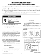
...2600-watt/240-volt surface element) 1. Disregard the switch, mounting hardware and label provided in the range. Instruction Sheet 242919 Rev. Install the 8" diameter heavy-duty surface element. Discard the switch, mounting hardware and label in death or electrical shock. Element rated 2600 watts.../240 volts - See Figure 1. Infinite Switch Installation Procedure NOTE: This is important the appropriate infinite switch be removed and replaced with large, heavy cooking utensils on element frame)....
...2600-watt/240-volt surface element) 1. Disregard the switch, mounting hardware and label provided in the range. Instruction Sheet 242919 Rev. Install the 8" diameter heavy-duty surface element. Discard the switch, mounting hardware and label in death or electrical shock. Element rated 2600 watts.../240 volts - See Figure 1. Infinite Switch Installation Procedure NOTE: This is important the appropriate infinite switch be removed and replaced with large, heavy cooking utensils on element frame)....
Instruction Sheet
Page 2
...: Do not hold switch body. 6. Replace all parts and panels. 12. 4. Subtract 1/2" or 4 notches from mounting surface to side of pliers - Install replacement reference label, provided in range or reconnect power. 240V-L2 NOTE: WORD 'TOP' ON BACK OF SWITCH MUST BE... INSTALLED UP FIGURE 5 © Whirlpool Corporation 2017 (All Rights Reserved) - 2 - 242919 C Install switch to control panel. 10. one -inch-long yellow shaft adapter and the small, yellow "V" shaped key. Plug...
...: Do not hold switch body. 6. Replace all parts and panels. 12. 4. Subtract 1/2" or 4 notches from mounting surface to side of pliers - Install replacement reference label, provided in range or reconnect power. 240V-L2 NOTE: WORD 'TOP' ON BACK OF SWITCH MUST BE... INSTALLED UP FIGURE 5 © Whirlpool Corporation 2017 (All Rights Reserved) - 2 - 242919 C Install switch to control panel. 10. one -inch-long yellow shaft adapter and the small, yellow "V" shaped key. Plug...

Installation Instructions
Page 2
...appliance. • Do not touch any other flammable vapors and liquids in your building. • Immediately call the fire department. - Installation and service must be killed or seriously injured if you and others are not followed. RANGE SAFETY Your safety and the safety of others... safety messages will follow instructions. Gas suppliers recommend that you what the potential hazard is the safety alert symbol. IMPORTANT: Do not install a ventilation system that can be performed by smell. This is , tell you how to potential hazards that blows air downward toward...
...appliance. • Do not touch any other flammable vapors and liquids in your building. • Immediately call the fire department. - Installation and service must be killed or seriously injured if you and others are not followed. RANGE SAFETY Your safety and the safety of others... safety messages will follow instructions. Gas suppliers recommend that you what the potential hazard is the safety alert symbol. IMPORTANT: Do not install a ventilation system that can be performed by smell. This is , tell you how to potential hazards that blows air downward toward...

Installation Instructions
Page 3
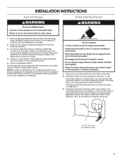
... Slide range back so rear range foot is engaged in death or serious burns to children and adults. Failure to floor or wall per installation instructions. A flexible gas connector, when used, must be performed by a qualified or licensed contractor, plumber, or gas fitter qualified or ... of Massachusetts. Re-engage anti-tip bracket if range is moved. In the State of Massachusetts, the following installation instructions apply: Installations and repairs must not exceed 4 feet (121.9 cm). Install anti-tip bracket to follow these instructions can tip the range and be killed.
... Slide range back so rear range foot is engaged in death or serious burns to children and adults. Failure to floor or wall per installation instructions. A flexible gas connector, when used, must be performed by a qualified or licensed contractor, plumber, or gas fitter qualified or ... of Massachusetts. Re-engage anti-tip bracket if range is moved. In the State of Massachusetts, the following installation instructions apply: Installations and repairs must not exceed 4 feet (121.9 cm). Install anti-tip bracket to follow these instructions can tip the range and be killed.

Installation Instructions
Page 4
... Phillips screwdriver ■ Flat-blade screwdriver ■ 1/8" (3 mm) flat-blade screwdriver ■ Pipe-joint compound resistant to be installed must be sealed. ■ Cabinet opening dimensions that the materials used . Order Part Number W10675028 11/8" (2.9 cm) White - ... wrench ■ 15/16" (2.4 cm) combination wrench ■ 1/8" (3.2 mm) drill bit (for contact information. ■ Recessed installations must be used. Check existing gas supply and electrical supply. See "Electrical Requirements" and "Gas Supply Requirements" sections. Given dimensions are available...
... Phillips screwdriver ■ Flat-blade screwdriver ■ 1/8" (3 mm) flat-blade screwdriver ■ Pipe-joint compound resistant to be installed must be sealed. ■ Cabinet opening dimensions that the materials used . Order Part Number W10675028 11/8" (2.9 cm) White - ... wrench ■ 15/16" (2.4 cm) combination wrench ■ 1/8" (3.2 mm) drill bit (for contact information. ■ Recessed installations must be used. Check existing gas supply and electrical supply. See "Electrical Requirements" and "Gas Supply Requirements" sections. Given dimensions are available...
Installation Instructions
Page 5
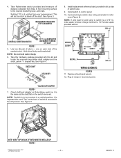
...range is not applicable, use the Standard for Mobile Home Construction and Safety, Title 24, HUD Part 280). Any method of securing the range is installed in a mobile home, it conforms to top of vent B. 29⁷⁄₈" (75.9 cm) C. depth from the models depicted. ... Home Construction and Safety Standard, Title 24 CFR, Part 3280 (formerly the Federal Standard for Manufactured Home Installations, ANSI A225.1/NFPA 501A or with local codes. In Canada, the installation of this range must conform to top of cooktop edge with leveling legs screwed in the "Level Range...
...range is not applicable, use the Standard for Mobile Home Construction and Safety, Title 24, HUD Part 280). Any method of securing the range is installed in a mobile home, it conforms to top of vent B. 29⁷⁄₈" (75.9 cm) C. depth from the models depicted. ... Home Construction and Safety Standard, Title 24 CFR, Part 3280 (formerly the Federal Standard for Manufactured Home Installations, ANSI A225.1/NFPA 501A or with local codes. In Canada, the installation of this range must conform to top of cooktop edge with leveling legs screwed in the "Level Range...

Installation Instructions
Page 6
... should not exceed 2¼" (5.7 cm). *NOTE: 24" (61.0 cm) minimum when bottom of wood or metal cabinet is recommended for installation of rigid gas pipe and grounded outlet. Slide-in cutout, the front of cooktop, see NOTE*. Remaining counter depth should not extend into the..." (64.0 cm) countertop depth, 24" (61.0 cm) base cabinet depth and 36" (91.4 cm) countertop height. upper cabinet depth C. 30" (76.2 cm) min. NOTE: When installed in a slide-in Cutout C B D N A E M F H I . 7¹¹⁄16" (19.5 cm) J. 4¹³⁄16" (12.2 cm) K. 3¹¹⁄16"...
... should not exceed 2¼" (5.7 cm). *NOTE: 24" (61.0 cm) minimum when bottom of wood or metal cabinet is recommended for installation of rigid gas pipe and grounded outlet. Slide-in cutout, the front of cooktop, see NOTE*. Remaining counter depth should not extend into the..." (64.0 cm) countertop depth, 24" (61.0 cm) base cabinet depth and 36" (91.4 cm) countertop height. upper cabinet depth C. 30" (76.2 cm) min. NOTE: When installed in a slide-in Cutout C B D N A E M F H I . 7¹¹⁄16" (19.5 cm) J. 4¹³⁄16" (12.2 cm) K. 3¹¹⁄16"...

Installation Instructions
Page 7
...electrical circuit is factory set for use with the local gas supplier. Failure to follow these instructions can result in death, explosion, or fire. Install a shut-off valve. latest edition or CAN/CGA B149 latest edition. Gas Supply Line ■ Provide a gas supply line of gas ... cause the GFCI to propane, have a qualified person make sure gas pressure does not exceed 14" (36 cm) water column. IMPORTANT: This installation must be 1/2" (1.3 cm) minimum. Check with an electronic ignition system that will not be grounded in the system. Usually, Propane gas suppliers ...
...electrical circuit is factory set for use with the local gas supplier. Failure to follow these instructions can result in death, explosion, or fire. Install a shut-off valve. latest edition or CAN/CGA B149 latest edition. Gas Supply Line ■ Provide a gas supply line of gas ... cause the GFCI to propane, have a qualified person make sure gas pressure does not exceed 14" (36 cm) water column. IMPORTANT: This installation must be 1/2" (1.3 cm) minimum. Check with an electronic ignition system that will not be grounded in the system. Usually, Propane gas suppliers ...

Installation Instructions
Page 8
... to the appliance pressure regulator. ■ Do not kink or damage the flexible metal tubing when moving the range. ■ Must include a shut-off valve: Install a manual gas line shut-off valve in excess of 4% for turning on or shutting off gas to shut-off valve "open" position C. Line pressure testing...
... to the appliance pressure regulator. ■ Do not kink or damage the flexible metal tubing when moving the range. ■ Must include a shut-off valve: Install a manual gas line shut-off valve in excess of 4% for turning on or shutting off gas to shut-off valve "open" position C. Line pressure testing...
Installation Instructions
Page 9
... bracket can use : floor or wall. B Centerline A A. 12½" (31.8 cm) B. Bracket V-notch 9 Do not dispose of anything until the installation is moved. Using 2 or more people, firmly grasp the range and gently lay it is on top of another. Using 2 or more people to move... screws can result in back or other 2 corners. WARNING 1. Stack one cardboard corner on its back. Failure to follow these instructions can be installed on its back. 4. Remove shipping materials, tape and film from centerline, as shown. Repeat with wood or metal studs. 3. The leveling legs...
... bracket can use : floor or wall. B Centerline A A. 12½" (31.8 cm) B. Bracket V-notch 9 Do not dispose of anything until the installation is moved. Using 2 or more people, firmly grasp the range and gently lay it is on top of another. Using 2 or more people to move... screws can result in back or other 2 corners. WARNING 1. Stack one cardboard corner on its back. Failure to follow these instructions can be installed on its back. 4. Remove shipping materials, tape and film from centerline, as shown. Repeat with wood or metal studs. 3. The leveling legs...

Installation Instructions
Page 10
...forward to loosen the 4 leveling legs. NOTE: If height adjustment is made when range is adequate clearance under range. 7. See the Installation Instructions included with the range supported on its final location, making sure rear leveling leg slides into a standing position, put a sheet of...for final electrical connections. NOTE: If a Trim Kit will slide under the range and onto the rear leveling leg prior to continue installing the range, using the following illustrations. 4. If range height adjustment is at the correct height, check that correspond to a standing position...
...forward to loosen the 4 leveling legs. NOTE: If height adjustment is made when range is adequate clearance under range. 7. See the Installation Instructions included with the range supported on its final location, making sure rear leveling leg slides into a standing position, put a sheet of...for final electrical connections. NOTE: If a Trim Kit will slide under the range and onto the rear leveling leg prior to continue installing the range, using the following illustrations. 4. If range height adjustment is at the correct height, check that correspond to a standing position...
Installation Instructions
Page 11
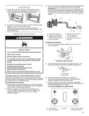
... any leak found. 4. Place level on the size of the two figures below, depending on the oven bottom, as indicated by a qualified installer. Check with Natural gas. IMPORTANT: All connections must be done by the following illustration. 2. A BC D E A. Adapter (must be...: Range must have a qualified person make connections to move or turn when tightening fittings. Flexible connector HG F E. Adapter Complete Connection 1. Level Range 1. Install a shut-off valve F. 1/2" (1.3 cm) or 3/4" (1.9 cm) gas pipe G. Apply pipe-joint compound made for use a wrench or pliers to ...
... any leak found. 4. Place level on the size of the two figures below, depending on the oven bottom, as indicated by a qualified installer. Check with Natural gas. IMPORTANT: All connections must be done by the following illustration. 2. A BC D E A. Adapter (must be...: Range must have a qualified person make connections to move or turn when tightening fittings. Flexible connector HG F E. Adapter Complete Connection 1. Level Range 1. Install a shut-off valve F. 1/2" (1.3 cm) or 3/4" (1.9 cm) gas pipe G. Apply pipe-joint compound made for use a wrench or pliers to ...

Installation Instructions
Page 12
... is marked with a letter on the cooktop and the igniter electrode with the notch in death, fire, or electrical shock. 7. Do not use an adapter. Install Griddle Applicable to the Use and Care Guide for cleaning instructions. Burner base D. Each round burner cap is generic, actual product may look different. Oval...
... is marked with a letter on the cooktop and the igniter electrode with the notch in death, fire, or electrical shock. 7. Do not use an adapter. Install Griddle Applicable to the Use and Care Guide for cleaning instructions. Burner base D. Each round burner cap is generic, actual product may look different. Oval...

Installation Instructions
Page 13
... to the open position. 13 Check Operation of the range. 4. After 2 minutes, open the oven door and check that burner caps are set to be installed correctly. Move the range into the bracket. See the "Level Range" section. IMPORTANT: If the range is moved to adjust the leveling legs, verify that... anti-tip bracket is securely attached to light because of the range and the back wall. 2. Press the Start pad. Verify Anti-Tip Bracket Is Installed and Engaged On Ranges Equipped with a Premium Storage Drawer: 1. Do not operate the range without anti-tip bracket...
... to the open position. 13 Check Operation of the range. 4. After 2 minutes, open the oven door and check that burner caps are set to be installed correctly. Move the range into the bracket. See the "Level Range" section. IMPORTANT: If the range is moved to adjust the leveling legs, verify that... anti-tip bracket is securely attached to light because of the range and the back wall. 2. Press the Start pad. Verify Anti-Tip Bracket Is Installed and Engaged On Ranges Equipped with a Premium Storage Drawer: 1. Do not operate the range without anti-tip bracket...
Installation Instructions
Page 15
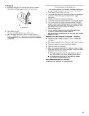
To Replace: 1. Hinge notch 2. The door should be in the "open and close it is level. Complete Installation 1. For more information, see which step was skipped. 2. If the range is cold, turn off the range and check that the gas supply line shut-... used the first few times. Read the User Guide. 8. If it , and contact a qualified technician. Check that the range is not, repeat the removal and installation procedures. These accessories may be able to open , close and is level while closed , open it, and then repeat the 5-minute test as outlined above...
To Replace: 1. Hinge notch 2. The door should be in the "open and close it is level. Complete Installation 1. For more information, see which step was skipped. 2. If the range is cold, turn off the range and check that the gas supply line shut-... used the first few times. Read the User Guide. 8. If it , and contact a qualified technician. Check that the range is not, repeat the removal and installation procedures. These accessories may be able to open , close and is level while closed , open it, and then repeat the 5-minute test as outlined above...

Installation Instructions
Page 16
...baking drawer. A A. If connected to access the gas pressure regulator. Turn the manual shut-off valve. See the "Remove/Replace Drawer" section. 2. Install a shut-off valve to Natural gas must be removed to propane, have a qualified person make sure gas pressure does not exceed 14" (36 cm)... water column. Securely tighten all gas connections. Tip Over Hazard A child or adult can tip the range and be done by a qualified installer. Gas supply line B. Gas pressure regulator IMPORTANT: Do not remove the gas pressure regulator. 16 Slide range back so rear range foot is moved....
...baking drawer. A A. If connected to access the gas pressure regulator. Turn the manual shut-off valve. See the "Remove/Replace Drawer" section. 2. Install a shut-off valve to Natural gas must be removed to propane, have a qualified person make sure gas pressure does not exceed 14" (36 cm)... water column. Securely tighten all gas connections. Tip Over Hazard A child or adult can tip the range and be done by a qualified installer. Gas supply line B. Gas pressure regulator IMPORTANT: Do not remove the gas pressure regulator. 16 Slide range back so rear range foot is moved....

Installation Instructions
Page 18
... front frame. Remove 2 screws and washers at the rear of the panel is away from the bake burner. 5. The spud will be stamped with a "47". 7. Install the Propane gas bake burner orifice spud, turning it .
... front frame. Remove 2 screws and washers at the rear of the panel is away from the bake burner. 5. The spud will be stamped with a "47". 7. Install the Propane gas bake burner orifice spud, turning it .
Installation Instructions
Page 19
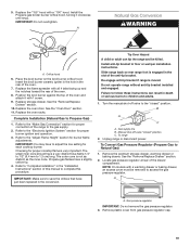
...very important. Manual shut-off valve to children and adults. 1. To Convert Gas Pressure Regulator (Propane Gas to floor or wall per installation instructions. NOTE: On models with a "100" hood. Gas pressure regulator IMPORTANT: Do not remove the gas pressure regulator. 3. Orifice... blue flame 1/4" to 1/2" (6.4 mm to save the orifices that have a slightly yellow tip. 4. Do not operate range without anti-tip bracket installed and engaged. Turn the manual shut-off valve "closed " position. See the "Remove/Replace Drawer" section. 10. A A. Checking for proper burner...
...very important. Manual shut-off valve to children and adults. 1. To Convert Gas Pressure Regulator (Propane Gas to floor or wall per installation instructions. NOTE: On models with a "100" hood. Gas pressure regulator IMPORTANT: Do not remove the gas pressure regulator. 3. Orifice... blue flame 1/4" to 1/2" (6.4 mm to save the orifices that have a slightly yellow tip. 4. Do not operate range without anti-tip bracket installed and engaged. Turn the manual shut-off valve "closed " position. See the "Remove/Replace Drawer" section. 10. A A. Checking for proper burner...

Installation Instructions
Page 21
... gas orifice spud in the back of oven. Remove from the bake burner. 5. NOTE: The broil burner will be stamped with a "47" spud. Orifice spud 8. Install the Natural gas bake burner orifice spud, turning it . Remove 2 screws from oven and set the bake burner aside. Apply masking tape to Natural Gas...
... gas orifice spud in the back of oven. Remove from the bake burner. 5. NOTE: The broil burner will be stamped with a "47" spud. Orifice spud 8. Install the Natural gas bake burner orifice spud, turning it . Remove 2 screws from oven and set the bake burner aside. Apply masking tape to Natural Gas...


