Installation Instructions
Page 1
Write down the model and serial numbers before installing cooktop. Installation Instructions 30" (76.2 cm) and 36" (91.4 cm) ELECTRIC Built-in Ceramic Downdraft Cooktop IMPORTANT: Read and save these instructions. Save Installation Instructions for future reference. Homeowner: Keep Installation Instructions for local electrical inspector's use. Model Serial Part No. 8286553 IMPORTANT: Installer: Leave Installation Instructions with the homeowner. Both numbers are on the model/serial rating plate, located on the bottom of the cooktop.
Write down the model and serial numbers before installing cooktop. Installation Instructions 30" (76.2 cm) and 36" (91.4 cm) ELECTRIC Built-in Ceramic Downdraft Cooktop IMPORTANT: Read and save these instructions. Save Installation Instructions for future reference. Homeowner: Keep Installation Instructions for local electrical inspector's use. Model Serial Part No. 8286553 IMPORTANT: Installer: Leave Installation Instructions with the homeowner. Both numbers are on the model/serial rating plate, located on the bottom of the cooktop.
Installation Instructions
Page 2
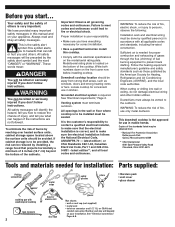
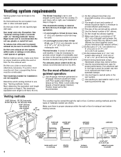
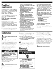
... word "DANGER" or "WARNING". Number and size will be reduced by installing a range hood that projects horizontally a minimum of 5 inches (12.7 cm) beyond the bottom of the cooktop. We have everything necessary for convenient use in this cooktop. • Comply with the electrical specifications on the bottom of the cabinets. When cutting or drilling into...
... word "DANGER" or "WARNING". Number and size will be reduced by installing a range hood that projects horizontally a minimum of 5 inches (12.7 cm) beyond the bottom of the cooktop. We have everything necessary for convenient use in this cooktop. • Comply with the electrical specifications on the bottom of the cabinets. When cutting or drilling into...
Installation Instructions
Page 3
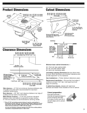
...box depth 15-5/8" (39.6 cm) blower housing depth 3-ft. (91.4 cm) long power supply cable factory installed. countertop Install rear wall junction box in shaded area. Minimum base cabinet dimensions - 30" (76.2 cm) base cabinet width 24" (61 cm) base cabinet depth 25" (63.5 cm) ...for exhaust duct cutout location). 2" (5.1 cm) minimum space to front edge of countertop Countertop must be removed and drawer fronts installed on front of cooktop and rear wall is recommended. Follow minimum dimensions given. Chamfer all exposed edges to prevent cracking. 3 Given dimensions are shown...
...box depth 15-5/8" (39.6 cm) blower housing depth 3-ft. (91.4 cm) long power supply cable factory installed. countertop Install rear wall junction box in shaded area. Minimum base cabinet dimensions - 30" (76.2 cm) base cabinet width 24" (61 cm) base cabinet depth 25" (63.5 cm) ...for exhaust duct cutout location). 2" (5.1 cm) minimum space to front edge of countertop Countertop must be removed and drawer fronts installed on front of cooktop and rear wall is recommended. Follow minimum dimensions given. Chamfer all exposed edges to prevent cracking. 3 Given dimensions are shown...
Installation Instructions
Page 4
...galvanized or 25-gauge minimum aluminum metal vent. Venting methods 9-5/8" (24.4 cm) - 30" (76.2 cm) model 13-5/16" (33.8 cm) - 36" (91.4 cm)... or overhang directly outside between the elbows if more than 10 feet (3 m), use 4-inch (10 cm) laundry-type wall caps. Exception: See "optional venting under a concrete ... then a supporting frame must terminate to vent straight out the back from the cooktop. Do Not use 6" (15.2 cm) diameter round or 3-1/4" x 10" ... air outside 4 To vent down, left or right, see "Installation," Step 2, Page 6. Common venting methods and the types of fire...
...galvanized or 25-gauge minimum aluminum metal vent. Venting methods 9-5/8" (24.4 cm) - 30" (76.2 cm) model 13-5/16" (33.8 cm) - 36" (91.4 cm)... or overhang directly outside between the elbows if more than 10 feet (3 m), use 4-inch (10 cm) laundry-type wall caps. Exception: See "optional venting under a concrete ... then a supporting frame must terminate to vent straight out the back from the cooktop. Do Not use 6" (15.2 cm) diameter round or 3-1/4" x 10" ... air outside 4 To vent down, left or right, see "Installation," Step 2, Page 6. Common venting methods and the types of fire...
Installation Instructions
Page 6
...cooktop is centered in cutout. 6 supply is required on a separate 30-ampere circuit, fused on both sides of the cooktop. Connect vent system. Use 10-gauge solid copper wire. The recommended minimum copper wire size is No.-10 gauge. Complete electrical... of cooktop is at least 1-1/2" (38.1 mm) from front edge of downdraft cooktop is at least 6 inches (15.2 cm) from cutout when positioning cooktop in the...move and install cooktop. It may be obtained from cooktop. 2. or CSA-listed conduit connector are not sure cooktop is properly grounded. Make the electrical connection: ...
...cooktop is centered in cutout. 6 supply is required on a separate 30-ampere circuit, fused on both sides of the cooktop. Connect vent system. Use 10-gauge solid copper wire. The recommended minimum copper wire size is No.-10 gauge. Complete electrical... of cooktop is at least 1-1/2" (38.1 mm) from front edge of downdraft cooktop is at least 6 inches (15.2 cm) from cutout when positioning cooktop in the...move and install cooktop. It may be obtained from cooktop. 2. or CSA-listed conduit connector are not sure cooktop is properly grounded. Make the electrical connection: ...
Installation Instructions
Page 7
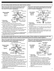
... screws on conduit connector. 4. Connect the bare cooktop wire with the white wire; For all cooktop models with three-wire cable from the cooktop: Where local codes Do Not permit connecting the frameground conductor to the neutral (white) junction box wire. (Not used for Canadian installations): Grounded neutral 3-wire cable from power supply red...
... screws on conduit connector. 4. Connect the bare cooktop wire with the white wire; For all cooktop models with three-wire cable from the cooktop: Where local codes Do Not permit connecting the frameground conductor to the neutral (white) junction box wire. (Not used for Canadian installations): Grounded neutral 3-wire cable from power supply red...
Installation Instructions
Page 8
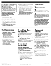
... ✓ Call the Customer Interaction Center. Replace the junction box cover. You have just finished installing your telephone directory under "Appliances - Reinstall cooktop in U.S.A. 04/2005 If cooktop does not operate: ✓ Check that the circuit breaker is not tripped or the house fuse .... 2. To get the most efficient use from your new cooktop, read your Use and Care Guide for easy reference. After cleaning and maintenance: 1. Connect electrical supply. Turn on electrical supply. 7. If the cooktop does not operate, disconnect the power supply and check that ...
... ✓ Call the Customer Interaction Center. Replace the junction box cover. You have just finished installing your telephone directory under "Appliances - Reinstall cooktop in U.S.A. 04/2005 If cooktop does not operate: ✓ Check that the circuit breaker is not tripped or the house fuse .... 2. To get the most efficient use from your new cooktop, read your Use and Care Guide for easy reference. After cleaning and maintenance: 1. Connect electrical supply. Turn on electrical supply. 7. If the cooktop does not operate, disconnect the power supply and check that ...
Use and Care Guide
Page 3
...s Glazed Cooking Utensils - s Do Not Cook on Cooktop - Contact a qualified technician immediately. Grease should never be immersed in water. s Make Sure Reflector Pans or Drip Bowls Are in burns from steam. Improper installation of electric shock, or fire. SAVE THESE INSTRUCTIONS 3 Children should ...never be worn while using the cooktop, follow basic precautions, including the following: s CAUTION: Do not store items ...
...s Glazed Cooking Utensils - s Do Not Cook on Cooktop - Contact a qualified technician immediately. Grease should never be immersed in water. s Make Sure Reflector Pans or Drip Bowls Are in burns from steam. Improper installation of electric shock, or fire. SAVE THESE INSTRUCTIONS 3 Children should ...never be worn while using the cooktop, follow basic precautions, including the following: s CAUTION: Do not store items ...
Use and Care Guide
Page 8
...warm. You may want to condition the cooktop. Continue rubbing until white film disappears. Scratches and abrasions do not affect cooking performance and after many cleanings become less noticeable. Do not soak knobs. Cleaning Method: s KitchenAid® Stainless Steel Cleaner & Polish ...appliance wired properly? Light to avoid damaging. If problem continues, call . See Installation Instructions. Hold scraper as flat as possible on some paper towels. Tiny scratches and abrasions s Cooktop Polishing Creme: Rub creme into soil with a damp paper towel or soft cloth....
...warm. You may want to condition the cooktop. Continue rubbing until white film disappears. Scratches and abrasions do not affect cooking performance and after many cleanings become less noticeable. Do not soak knobs. Cleaning Method: s KitchenAid® Stainless Steel Cleaner & Polish ...appliance wired properly? Light to avoid damaging. If problem continues, call . See Installation Instructions. Hold scraper as flat as possible on some paper towels. Tiny scratches and abrasions s Cooktop Polishing Creme: Rub creme into soil with a damp paper towel or soft cloth....
Use and Care Guide
Page 9
...to build every new KITCHENAID® appliance. Cooktop Cleaner (ceramic glass models) Order Part Number 31464 Cooktop Protectant Order Part Number 31463 If you need replacement parts If you need further assistance, you can also look in the United States. s Installation information. Our consultants... provide assistance with: s Features and specifications on cooktop s Is the cookware the proper size? For further assistance If you need help us ...
...to build every new KITCHENAID® appliance. Cooktop Cleaner (ceramic glass models) Order Part Number 31464 Cooktop Protectant Order Part Number 31463 If you need replacement parts If you need further assistance, you can also look in the United States. s Installation information. Our consultants... provide assistance with: s Features and specifications on cooktop s Is the cookware the proper size? For further assistance If you need help us ...
Use and Care Guide
Page 10
...installed in materials or workmanship: ■ Electric element ■ Gas burners ■ Solid state touch control system parts ■ Any cracking of the rubber seal between the ceramic glass cooktop and porcelain edge ■ Any cracking due to thermal shock of the ceramic glass cooktop...and is reported to KitchenAid within 30 days from the date of purchase. 6. The cost of repair or replacement under this limited warranty. After checking "Troubleshooting," you need service, first see the "Troubleshooting" section of God, improper installation, installation not in materials or...
...installed in materials or workmanship: ■ Electric element ■ Gas burners ■ Solid state touch control system parts ■ Any cracking of the rubber seal between the ceramic glass cooktop and porcelain edge ■ Any cracking due to thermal shock of the ceramic glass cooktop...and is reported to KitchenAid within 30 days from the date of purchase. 6. The cost of repair or replacement under this limited warranty. After checking "Troubleshooting," you need service, first see the "Troubleshooting" section of God, improper installation, installation not in materials or...
Parts Diagram
Page 2
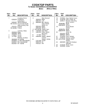
Part No. DESCRIPTION Illus. DESCRIPTION 1 Literature Parts 8286240 Installation Instructions 8286427 Wiring Diagram W10162163 Use & Care Guide Safe Cooking Tips 9762761 English W10065852 French 2 Cooktop, Glass 8286948 Black 8286985 White 3 3196537 Screw 4 3177991 Screw 5 Element, Surface 8523698 LR 1200W 8285846 LF 900/1800/2500W 8285937 RR ..., Vent Shield 24 8286055 Light, Hot Surface Indicator 25 3193094 Plate, Cover 26 3400093 Screw 2 W10240405 Part No. No. No. No. COOKTOP PARTS For Models: KECD806RBL05, KECD806RWW05 (Black) (White on White) Illus.
Part No. DESCRIPTION Illus. DESCRIPTION 1 Literature Parts 8286240 Installation Instructions 8286427 Wiring Diagram W10162163 Use & Care Guide Safe Cooking Tips 9762761 English W10065852 French 2 Cooktop, Glass 8286948 Black 8286985 White 3 3196537 Screw 4 3177991 Screw 5 Element, Surface 8523698 LR 1200W 8285846 LF 900/1800/2500W 8285937 RR ..., Vent Shield 24 8286055 Light, Hot Surface Indicator 25 3193094 Plate, Cover 26 3400093 Screw 2 W10240405 Part No. No. No. No. COOKTOP PARTS For Models: KECD806RBL05, KECD806RWW05 (Black) (White on White) Illus.


