Instruction Manual
Page 1
...serial numbers whenever you obtain the best performance from your Kenwood product at www.kenwoodusa.com © B64-3519-00/00 (KV) Model KAC-X20 Serial number US Residence Only Register Online Register your new power amplifier. Familiarity with installation and operation procedures will help you... call upon your Kenwood dealer for information or service on the warranty card, and...
...serial numbers whenever you obtain the best performance from your Kenwood product at www.kenwoodusa.com © B64-3519-00/00 (KV) Model KAC-X20 Serial number US Residence Only Register Online Register your new power amplifier. Familiarity with installation and operation procedures will help you... call upon your Kenwood dealer for information or service on the warranty card, and...
Instruction Manual
Page 2
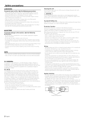
...cloth or a cloth dampened by one with the prescribed rating. When the protection function is triggered, the Power indicator goes OFF and the amplifier stops operating. • When a speaker wire may cause harmful interference unless the modifications are less than the maximum output power (in ... any metallic objects (such as an electrical ground passing electricity to the battery's negative - FCC WARNING This equipment may cause your Kenwood dealer. The user could lose the authority to operate this equipment does cause harmful interference to radio or television reception, which the ...
...cloth or a cloth dampened by one with the prescribed rating. When the protection function is triggered, the Power indicator goes OFF and the amplifier stops operating. • When a speaker wire may cause harmful interference unless the modifications are less than the maximum output power (in ... any metallic objects (such as an electrical ground passing electricity to the battery's negative - FCC WARNING This equipment may cause your Kenwood dealer. The user could lose the authority to operate this equipment does cause harmful interference to radio or television reception, which the ...
Instruction Manual
Page 3
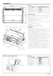
...-up occurs and the unit may cause injury or an accident. • After installing the unit, check to make sure that are blocked. Install the amplifier in a place where people, resins, and other damage. • Do not install near the dashboard, rear tray, or air bag safety parts. •...hot, In a place that gets direct sunlight, In a location that there is nothing hazardous on top of the unit. • The surface temperature of the amplifier will inhibit the cooling of Items 1 1 1 2 English 3 Once installed, do not place any object on the opposite side such as the brake lamps, ...
...-up occurs and the unit may cause injury or an accident. • After installing the unit, check to make sure that are blocked. Install the amplifier in a place where people, resins, and other damage. • Do not install near the dashboard, rear tray, or air bag safety parts. •...hot, In a place that gets direct sunlight, In a location that there is nothing hazardous on top of the unit. • The surface temperature of the amplifier will inhibit the cooling of Items 1 1 1 2 English 3 Once installed, do not place any object on the opposite side such as the brake lamps, ...
Instruction Manual
Page 4
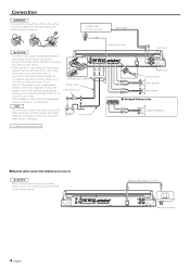
Terminal cover Battery wire* Protective Fuse* FUSE(30As2) POWER IN NOTE • Do not connect cables and leads to both RCA cable input jacks and the speaker level input terminals simultaneously, for shorts, then replace the fuse with one of the same rating. • Check that the brake lamps, winkers, and wipers work properly. CENTER UNIT (CD receiver, etc.) RCA cable* 2CAUTION • If sound is not output normally, immediately turn power off before changing the setting of any switch. • If the fuse blows, check wires for this unit to the left. 30 30 30 30 Connection ...
Terminal cover Battery wire* Protective Fuse* FUSE(30As2) POWER IN NOTE • Do not connect cables and leads to both RCA cable input jacks and the speaker level input terminals simultaneously, for shorts, then replace the fuse with one of the same rating. • Check that the brake lamps, winkers, and wipers work properly. CENTER UNIT (CD receiver, etc.) RCA cable* 2CAUTION • If sound is not output normally, immediately turn power off before changing the setting of any switch. • If the fuse blows, check wires for this unit to the left. 30 30 30 30 Connection ...
Instruction Manual
Page 5
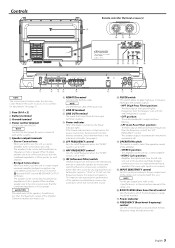
...become unnecessary oscillations, which affect the sound by eliminating unnecessary oscillations which the low frequency range should have an impedance of the amplifier. NOTE Use the Remote cable of the speakers by causing distortion, etc. This improves the reproduction performance of the accessory.... set with all the systems. 5 Speaker output terminals • Stereo Connections: When you wish to use as a high-output monaural amplifier, bridged connections are to "LPF". ! HPF FREQUENCY control Sets the cutoff frequency when the "FILTER" switch is output without filtering. ...
...become unnecessary oscillations, which affect the sound by eliminating unnecessary oscillations which the low frequency range should have an impedance of the amplifier. NOTE Use the Remote cable of the speakers by causing distortion, etc. This improves the reproduction performance of the accessory.... set with all the systems. 5 Speaker output terminals • Stereo Connections: When you wish to use as a high-output monaural amplifier, bridged connections are to "LPF". ! HPF FREQUENCY control Sets the cutoff frequency when the "FILTER" switch is output without filtering. ...
Instruction Manual
Page 6
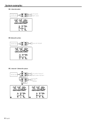
System examples ■ 2-channel system CENTER UNIT L L RR Left speaker Right speaker ■ Subwoofer system CENTER UNIT L L RR Subwoofer (Bridged) ■ 2-channel + Subwoofer system CENTER UNIT f L L RR LINE OUT L L RR LINE OUT g Left speaker (High pass) Right speaker (High pass) Subwoofer (L + R) (Bridged) f g 6 English
System examples ■ 2-channel system CENTER UNIT L L RR Left speaker Right speaker ■ Subwoofer system CENTER UNIT L L RR Subwoofer (Bridged) ■ 2-channel + Subwoofer system CENTER UNIT f L L RR LINE OUT L L RR LINE OUT g Left speaker (High pass) Right speaker (High pass) Subwoofer (L + R) (Bridged) f g 6 English
Instruction Manual
Page 7
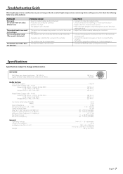
SOLUTION • Connect the input (or output) cables. • Check connections by referring to . • Connect the Remote Cable securely and correctly. Before calling service, first check the following table for possible problems. PROBLEM No sound. (No sound from one side.) (Blown fuse.) The output level is distorted.) The Remote Controller does not function. The sound quality is bad. (The sound is too small (or too large). CEA-2006 RMS Watts per channel @ 4 ohms, 1 % THD+N...180 W × 2 Signal to Noise Ratio (Reference: 1Watt into 4 ohms)...80 dBA Audio Section Max Power ...
SOLUTION • Connect the input (or output) cables. • Check connections by referring to . • Connect the Remote Cable securely and correctly. Before calling service, first check the following table for possible problems. PROBLEM No sound. (No sound from one side.) (Blown fuse.) The output level is distorted.) The Remote Controller does not function. The sound quality is bad. (The sound is too small (or too large). CEA-2006 RMS Watts per channel @ 4 ohms, 1 % THD+N...180 W × 2 Signal to Noise Ratio (Reference: 1Watt into 4 ohms)...80 dBA Audio Section Max Power ...
