User Guide
Page 4
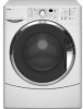
Page DIAGNOSTICS & TROUBLESHOOTING 6-1 Diagnostics 6-1 Diagnostic Guide 6-1 Failure/Error Display Codes 6-2 Diagnostic Test 6-5 Error History Display 6-6 History Overview Test Program 6-6 Manual Diagnostic Test 6-7 Manual Overview Test Program 6-7 Electronic Assemblies - Removal Or Replacement 6-8 Washer Care 6-9 Troubleshooting Guide 6-11 WIRING DIAGRAMS 7-1 Washer 7-1 Grounding System 7-2 - iv -
Page DIAGNOSTICS & TROUBLESHOOTING 6-1 Diagnostics 6-1 Diagnostic Guide 6-1 Failure/Error Display Codes 6-2 Diagnostic Test 6-5 Error History Display 6-6 History Overview Test Program 6-6 Manual Diagnostic Test 6-7 Manual Overview Test Program 6-7 Electronic Assemblies - Removal Or Replacement 6-8 Washer Care 6-9 Troubleshooting Guide 6-11 WIRING DIAGRAMS 7-1 Washer 7-1 Grounding System 7-2 - iv -
User Guide
Page 8
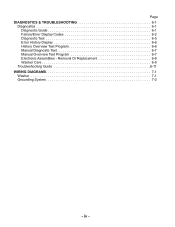
SPECIFICATIONS Model Number Model Description Color Capacity (Cu.Ft. Max Width Product Weight (approx) WFW8300SW WFW8500SW WFW8500SR Front Load Washer Front Load Washer Front Load Washer White with Gray Accents White with Gray Accents White with Sterling Bright Accents 3.3 3.6 3.6 ATC - 2 ATC - 4 ATC - 4 No Yes Yes Suds Sensor, NTC ...; 1/4 HP 120V 120V 120V 60 Hz 60 Hz 60 Hz 10 Amp 10 Amp 10 Amp 12.77 14.1 14.1 15.43 lbs. (7 kg) Maximum = 11.7 Average = 7.35 Minimum = 3 36.0" 29.25" 27" 242 lbs. 17.64 lbs. (8 kg) N/A 36.0" 30.00" 27" 242 lbs. 17.64 lbs. (8 ...
SPECIFICATIONS Model Number Model Description Color Capacity (Cu.Ft. Max Width Product Weight (approx) WFW8300SW WFW8500SW WFW8500SR Front Load Washer Front Load Washer Front Load Washer White with Gray Accents White with Gray Accents White with Sterling Bright Accents 3.3 3.6 3.6 ATC - 2 ATC - 4 ATC - 4 No Yes Yes Suds Sensor, NTC ...; 1/4 HP 120V 120V 120V 60 Hz 60 Hz 60 Hz 10 Amp 10 Amp 10 Amp 12.77 14.1 14.1 15.43 lbs. (7 kg) Maximum = 11.7 Average = 7.35 Minimum = 3 36.0" 29.25" 27" 242 lbs. 17.64 lbs. (8 kg) N/A 36.0" 30.00" 27" 242 lbs. 17.64 lbs. (8 ...
User Guide
Page 29
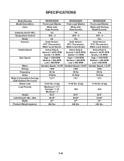
...Cycle Signal 3-11 Whitest Whites Soiled white fabrics Heavy Duty Heavily soiled underwear, towels, shirts, etc., made of cotton Normal/Casual Normally soiled blouses, shirts, overalls, etc., made of polyester, nylon, cotton, linen, or cotton blends Quick Wash Small loads of 2-3 ..., and special care items marked "Hand Washable" Clean Washer No clothes Rinse & Spin All loads Drain & Spin All loads Soak All loads Delay Wash AVAILABLE OPTIONS Extra Rinse Pre End of these washer cycles. CYCLE SUGGESTED LOAD TYPE Sanitary Heavily soiled underwear, towels, work cloths, ...
...Cycle Signal 3-11 Whitest Whites Soiled white fabrics Heavy Duty Heavily soiled underwear, towels, shirts, etc., made of cotton Normal/Casual Normally soiled blouses, shirts, overalls, etc., made of polyester, nylon, cotton, linen, or cotton blends Quick Wash Small loads of 2-3 ..., and special care items marked "Hand Washable" Clean Washer No clothes Rinse & Spin All loads Drain & Spin All loads Soak All loads Delay Wash AVAILABLE OPTIONS Extra Rinse Pre End of these washer cycles. CYCLE SUGGESTED LOAD TYPE Sanitary Heavily soiled underwear, towels, work cloths, ...
User Guide
Page 49
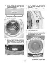
... from the door switch assembly. Screws 11. Open the washer door. Top Screws Retaining Wire Tension Spring 4-11 Front Panel Bottom Screws Continued on the retaining wire out from around the front of long-nosed pliers, pull the tension spring on the next page. Lower Front Access Panel 13. Close the washer door. 16. Remove the four...
... from the door switch assembly. Screws 11. Open the washer door. Top Screws Retaining Wire Tension Spring 4-11 Front Panel Bottom Screws Continued on the retaining wire out from around the front of long-nosed pliers, pull the tension spring on the next page. Lower Front Access Panel 13. Close the washer door. 16. Remove the four...
User Guide
Page 52
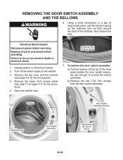
...pair of long-nosed pliers, pull the tension spring on page 4-11 for the procedures). 4. Replace all parts and panels before servicing. Unplug washer or disconnect power. 2. Failure to the washer. 3. Remove the lower front access panel (see page 4-2 for the procedure). 5. b) Remove... the two T-20 Torx screws from around the front of the front panel beside the door switch assembly...
...pair of long-nosed pliers, pull the tension spring on page 4-11 for the procedures). 4. Replace all parts and panels before servicing. Unplug washer or disconnect power. 2. Failure to the washer. 3. Remove the lower front access panel (see page 4-2 for the procedure). 5. b) Remove... the two T-20 Torx screws from around the front of the front panel beside the door switch assembly...
User Guide
Page 53
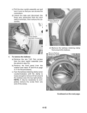
Remove Bellows Retaining Clamp Continued on page 4-11 for the procedure). d) Remove the bellows retaining clamp from around the bellows (see the top right photo). d) Unlock the tabs and disconnect the three wire ... Screw 3 Door Switch Assembly Connectors 8. NOTE: It may be necessary to remove it over so that you can access the connectors. b) Remove the front panel from the washer (see the photo in step 7b). c) Turn the bellows retaining clamp screw counterclockwise until the clamp is loose enough to completely remove the screw...
Remove Bellows Retaining Clamp Continued on page 4-11 for the procedure). d) Remove the bellows retaining clamp from around the bellows (see the top right photo). d) Unlock the tabs and disconnect the three wire ... Screw 3 Door Switch Assembly Connectors 8. NOTE: It may be necessary to remove it over so that you can access the connectors. b) Remove the front panel from the washer (see the photo in step 7b). c) Turn the bellows retaining clamp screw counterclockwise until the clamp is loose enough to completely remove the screw...
User Guide
Page 55
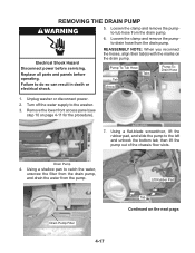
... pumpto-tub hose from the drain pump. Replace all parts and panels before servicing. Remove the lower front access panel (see step 10 on the drain pump. Loosen the clamp and remove the pumpto-drain... 6. REASSEMBLY NOTE: When you reconnect the hoses, align their tab(s) with the marks on page 4-11 for the procedure). 7. Pump-To-Tub Hose Tab Arrow Tabs Pump-ToDrain Hose 1. Turn off the ... Pump Filter 4-17 Lift Rubber Pad Tab Continued on the next page. Using a shallow pan to the washer. 3. Failure to the left and unhook the bottom tab, then lift the pump out of the chassis ...
... pumpto-tub hose from the drain pump. Replace all parts and panels before servicing. Remove the lower front access panel (see step 10 on the drain pump. Loosen the clamp and remove the pumpto-drain... 6. REASSEMBLY NOTE: When you reconnect the hoses, align their tab(s) with the marks on page 4-11 for the procedure). 7. Pump-To-Tub Hose Tab Arrow Tabs Pump-ToDrain Hose 1. Turn off the ... Pump Filter 4-17 Lift Rubber Pad Tab Continued on the next page. Using a shallow pan to the washer. 3. Failure to the left and unhook the bottom tab, then lift the pump out of the chassis ...
User Guide
Page 57
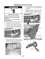
... tub and drain pump. Pump-To-Tub Hose Pump Clamp Drain Pump Filter 4-19 ECO Valve Replace all parts and panels before servicing. Unplug washer or disconnect power. 2. Electrical Shock Hazard Disconnect power before operating. REMOVING THE ECO VALVE 5. Pressure Hose Tub Clamp Air Trap Drain Pump 4....shock. 1. Using a shallow pan to -tub/ECO valve hose. 6. Remove the lower front access panel (see step 10 on page 4-11 for the procedure). Pull the pressure hose off the water supply to the washer. 3. Turn off the air trap that is connected to the pump-to catch the water...
... tub and drain pump. Pump-To-Tub Hose Pump Clamp Drain Pump Filter 4-19 ECO Valve Replace all parts and panels before servicing. Unplug washer or disconnect power. 2. Electrical Shock Hazard Disconnect power before operating. REMOVING THE ECO VALVE 5. Pressure Hose Tub Clamp Air Trap Drain Pump 4....shock. 1. Using a shallow pan to -tub/ECO valve hose. 6. Remove the lower front access panel (see step 10 on page 4-11 for the procedure). Pull the pressure hose off the water supply to the washer. 3. Turn off the air trap that is connected to the pump-to catch the water...
User Guide
Page 63
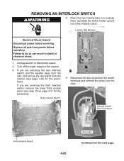
...Disconnect the two wires from the switch terminals and unhook the wires from the washer (see step 10 on the next page. Interlock Switch Wire Connectors Front Interlock Switch 4-25 Wire Clips Continued on page 4-11 for the procedure). Press the two locking tabs in to do so can result... panels before servicing. If you are servicing the front interlock switch, remove the lower front access panel (see page 4-20 for the procedure). Turn off the water supply to the washer. 3. If you are servicing the rear interlock switch, pull the washer away from the wall, and remove the rear...
...Disconnect the two wires from the switch terminals and unhook the wires from the washer (see step 10 on the next page. Interlock Switch Wire Connectors Front Interlock Switch 4-25 Wire Clips Continued on page 4-11 for the procedure). Press the two locking tabs in to do so can result... panels before servicing. If you are servicing the front interlock switch, remove the lower front access panel (see page 4-20 for the procedure). Turn off the water supply to the washer. 3. If you are servicing the rear interlock switch, pull the washer away from the wall, and remove the rear...
User Guide
Page 67
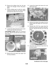
... Screw Bearing Hub 17. Disconnect the pressure hose from the drain pump. Remove the bellows from the basket shaft (see page 4-27 for the procedure). 11. Loosen the clamp and remove the vent tube-to the bearing hub, and pull the wire out of the tub holes. Remove the basket drive...
... Screw Bearing Hub 17. Disconnect the pressure hose from the drain pump. Remove the bellows from the basket shaft (see page 4-27 for the procedure). 11. Loosen the clamp and remove the vent tube-to the bearing hub, and pull the wire out of the tub holes. Remove the basket drive...

User Guide
Page 68
...18. b) Using a pair of pliers, turn . 22. To remove a shock absorber: a) Remove the 11/16˝ (17 mm) mounting bolt and nut from the tub. Squeeze in the tub, and remove the shock absorber... NOTE: When you reinstall the shock absorbers in the base mounting brackets, tighten the nut until it front-side down on the standoff tabs to release the standoffs. Remove the end of the shock absorber 90... the slots in on a padded surface. Remove the temperature sensor and heater from the washer, and place it contacts the bracket, then turn the nut an additional 1/4-turn the top of the vent...
...18. b) Using a pair of pliers, turn . 22. To remove a shock absorber: a) Remove the 11/16˝ (17 mm) mounting bolt and nut from the tub. Squeeze in the tub, and remove the shock absorber... NOTE: When you reinstall the shock absorbers in the base mounting brackets, tighten the nut until it front-side down on the standoff tabs to release the standoffs. Remove the end of the shock absorber 90... the slots in on a padded surface. Remove the temperature sensor and heater from the washer, and place it contacts the bracket, then turn the nut an additional 1/4-turn the top of the vent...
User Guide
Page 82
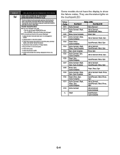
...to spin or drain again. Check wire harness connections to show the failure codes. Check drain pump. 7. Check the pressure switch. 8. Unplug washer or disconnect power. 3. Some models do not have the display to the drain pump, pressure switch, and Central Control Unit (CCU). 4.... They use the status lights on the touchpad/LED. Failure Codes Status LEDs Duet Sport Duet Sport Ht F/01 Add a Garment Add a Garment F/11 Add a Garment, Wash, Spin Add a Garment, Soak/Prewash, Rinse F/20 Rinse, Cycle Complete Wash, Spin F/21 Add a Garment, Rinse, Cycle Complete...
...to spin or drain again. Check wire harness connections to show the failure codes. Check drain pump. 7. Check the pressure switch. 8. Unplug washer or disconnect power. 3. Some models do not have the display to the drain pump, pressure switch, and Central Control Unit (CCU). 4.... They use the status lights on the touchpad/LED. Failure Codes Status LEDs Duet Sport Duet Sport Ht F/01 Add a Garment Add a Garment F/11 Add a Garment, Wash, Spin Add a Garment, Soak/Prewash, Rinse F/20 Rinse, Cycle Complete Wash, Spin F/21 Add a Garment, Rinse, Cycle Complete...
User Guide
Page 89
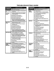
... by running a Diagnostic Test or any cycle. 1. If door is plugged into a working outlet and for operations of the drive motor. 6-11 WON'T SHUT OFF 1. Check harness connections. 7. Check installation. Verify hot and cold water faucets are unobstructed. Check drain pump motor. 8. ...Check pump drain system - Check drive belt. 2. Plug in washer or reconnect power. 7. Check the MCU by selecting different cycles and changing the modifiers and options available to confirm the touchpad/LED is ...
... by running a Diagnostic Test or any cycle. 1. If door is plugged into a working outlet and for operations of the drive motor. 6-11 WON'T SHUT OFF 1. Check harness connections. 7. Check installation. Verify hot and cold water faucets are unobstructed. Check drain pump motor. 8. ...Check pump drain system - Check drive belt. 2. Plug in washer or reconnect power. 7. Check the MCU by selecting different cycles and changing the modifiers and options available to confirm the touchpad/LED is ...
User Guide
Page 91
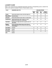
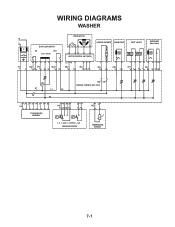
WIRING DIAGRAMS WASHER N L IF DOOR LOCK/SWITCH DS DLS Lock Unlock IF2 DS2 DL3 DLS2 1 2 12 1 2 3 1 2 DRIVE MOTOR MOTOR CONTROL UNIT (MCU) L2 N1 MS2 1 2 MI3 1 2 3 HEATING ELEMENT DRAIN PUMP INLET VALVES DISPENSER Motor Switch VC VH HE2 21 DP2 1 2 VH7 1 3 DI6 571 3 56 DR1 K1 L1 L2 K2 N1 HR2 HR1 CENTRAL CONTROL UNIT (CCU) 12 34 5 6 7 8 UI8 TOUCHPAD/LED ASSEMBLY 6 5 34 PR6 22 24 26 21 2 1 11 14 p> p> L_0 L_wash L_overflow L_sud PRESSURE SWITCH 1 2 TH2 TEMPERATURE SENSOR 7-1
WIRING DIAGRAMS WASHER N L IF DOOR LOCK/SWITCH DS DLS Lock Unlock IF2 DS2 DL3 DLS2 1 2 12 1 2 3 1 2 DRIVE MOTOR MOTOR CONTROL UNIT (MCU) L2 N1 MS2 1 2 MI3 1 2 3 HEATING ELEMENT DRAIN PUMP INLET VALVES DISPENSER Motor Switch VC VH HE2 21 DP2 1 2 VH7 1 3 DI6 571 3 56 DR1 K1 L1 L2 K2 N1 HR2 HR1 CENTRAL CONTROL UNIT (CCU) 12 34 5 6 7 8 UI8 TOUCHPAD/LED ASSEMBLY 6 5 34 PR6 22 24 26 21 2 1 11 14 p> p> L_0 L_wash L_overflow L_sud PRESSURE SWITCH 1 2 TH2 TEMPERATURE SENSOR 7-1
