User Guide
Page 3
... INFORMATION 2-1 Installation Requirements 2-1 Installation Instructions 2-6 PRODUCT OPERATION 3-1 Features And Benefits 3-1 Washer Use 3-3 Washer Care 3-12 Troubleshooting 3-15 COMPONENT ACCESS 4-1 Component Locations 4-1 Removing The Console And The Touchpad/LED Assembly 4-2 Removing The Central Control Unit 4-4 Removing The Water Inlet Valve 4-6 Removing The Pressure Switch 4-7 Removing The Line Filter & Power Supply Cord 4-8 Removing The Detergent Dispenser...
... INFORMATION 2-1 Installation Requirements 2-1 Installation Instructions 2-6 PRODUCT OPERATION 3-1 Features And Benefits 3-1 Washer Use 3-3 Washer Care 3-12 Troubleshooting 3-15 COMPONENT ACCESS 4-1 Component Locations 4-1 Removing The Console And The Touchpad/LED Assembly 4-2 Removing The Central Control Unit 4-4 Removing The Water Inlet Valve 4-6 Removing The Pressure Switch 4-7 Removing The Line Filter & Power Supply Cord 4-8 Removing The Detergent Dispenser...
User Guide
Page 39
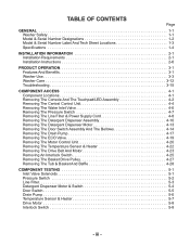
COMPONENT LOCATIONS Water Inlet Valve Line Filter Detergent Dispenser Motor & Assembly Pressure Switch Central Control Unit Temperature Sensor (On Rear Of Tub) Heater (On Rear Of Tub) Basket Tub Assembly Drive Motor Front Interlock Switch Not Shown: Console, Touchpad/LED Assembly, & Door Switch Assembly Rear Interlock Switch ECO Valve Motor Control Unit Drain Pump 4-1 The components and their locations are shown below. COMPONENT ACCESS This section instructs you on how to service each component inside the Duet Sport™ Front-Loading Automatic Washer.
COMPONENT LOCATIONS Water Inlet Valve Line Filter Detergent Dispenser Motor & Assembly Pressure Switch Central Control Unit Temperature Sensor (On Rear Of Tub) Heater (On Rear Of Tub) Basket Tub Assembly Drive Motor Front Interlock Switch Not Shown: Console, Touchpad/LED Assembly, & Door Switch Assembly Rear Interlock Switch ECO Valve Motor Control Unit Drain Pump 4-1 The components and their locations are shown below. COMPONENT ACCESS This section instructs you on how to service each component inside the Duet Sport™ Front-Loading Automatic Washer.
User Guide
Page 43
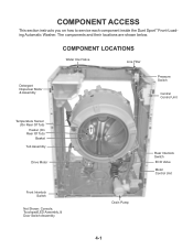
... 2 BK Wires Not Used No Stripe MI3 Serial Com 3 BU Wires Red Stripe Not Used UI8 - Door Lock Switch BK Stripe CENTRAL CONTROL UNIT Connector Locking Tabs 4-5 Door Switch 2 BU Wires Blue Stripe PR6 - Pressure Switch Not Used 6 BU Wires TH2 - Dispenser 4 BU Wires BU Stripe VCH7 - Heater MS2 - REASSEMBLY NOTE: The photo shows...
... 2 BK Wires Not Used No Stripe MI3 Serial Com 3 BU Wires Red Stripe Not Used UI8 - Door Lock Switch BK Stripe CENTRAL CONTROL UNIT Connector Locking Tabs 4-5 Door Switch 2 BU Wires Blue Stripe PR6 - Pressure Switch Not Used 6 BU Wires TH2 - Dispenser 4 BU Wires BU Stripe VCH7 - Heater MS2 - REASSEMBLY NOTE: The photo shows...
User Guide
Page 45
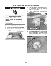
... panels before servicing. Turn off the pressure switch fitting. Remove the top cover from the washer. Turn the pressure switch 90° in a clockwise (CW) direction, and align the key on the switch with the slot in death or electrical shock. Pressure Switch Pressure Hose 6. REMOVING THE PRESSURE SWITCH 4. Turn 90° CW To Remove 4-7 Unplug washer or disconnect power. 2. Press and...
... panels before servicing. Turn off the pressure switch fitting. Remove the top cover from the washer. Turn the pressure switch 90° in a clockwise (CW) direction, and align the key on the switch with the slot in death or electrical shock. Pressure Switch Pressure Hose 6. REMOVING THE PRESSURE SWITCH 4. Turn 90° CW To Remove 4-7 Unplug washer or disconnect power. 2. Press and...
User Guide
Page 67
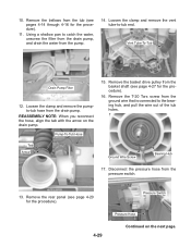
Loosen the clamp and remove the pumpto-tub hose from the pressure switch. 13. Disconnect the pressure hose from the drain pump. Vent Tube-To-Tub Drain Pump Filter 12. Tab Arrow Ground Wire Screw Bearing Hub 17. Remove the rear panel (..., align the tab with the arrow on the next page. Remove the basket drive pulley from the tub (see page 4-27 for the procedure). 4-29 Pressure Switch Pressure Hose Continued on the drain pump. Using a shallow pan to the bearing hub, and pull the wire out of the tub holes. Loosen the clamp...
Loosen the clamp and remove the pumpto-tub hose from the pressure switch. 13. Disconnect the pressure hose from the drain pump. Vent Tube-To-Tub Drain Pump Filter 12. Tab Arrow Ground Wire Screw Bearing Hub 17. Remove the rear panel (..., align the tab with the arrow on the next page. Remove the basket drive pulley from the tub (see page 4-27 for the procedure). 4-29 Pressure Switch Pressure Hose Continued on the drain pump. Using a shallow pan to the bearing hub, and pull the wire out of the tub holes. Loosen the clamp...
User Guide
Page 72
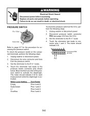
... do so can result in death or electrical shock. Set the ohmmeter to the pressure switch connector pins shown below. Electrical Shock Hazard Disconnect power before operating. Replace all parts and panels before accessing. Unplug washer or disconnect power. 2. Water Level Setting Empty Suds Detect L1 Overflow Test Points Pins 4 and 6 Pins 1 and...
... do so can result in death or electrical shock. Set the ohmmeter to the pressure switch connector pins shown below. Electrical Shock Hazard Disconnect power before operating. Replace all parts and panels before accessing. Unplug washer or disconnect power. 2. Water Level Setting Empty Suds Detect L1 Overflow Test Points Pins 4 and 6 Pins 1 and...
User Guide
Page 80
...water valves turn off. Check connection to step 7. 7. Check the MCU by all hoses for possible leaks. 6. Unplug washer or disconnect power. 4. Verify pressure switch operation. 8. Check the water temperature sensor and connection to lock the door. Possible Causes/Procedure A power glitch may ...heater. 3. FAILURE/ERROR DISPLAY CODES Communication of failure codes will be displayed. Replace the pump. Unplug washer or disconnect power. 2. Make sure that the pressure switch hose is running a Diagnostic Test or any cycle. Check the drain pump filter for operations of ...
...water valves turn off. Check connection to step 7. 7. Check the MCU by all hoses for possible leaks. 6. Unplug washer or disconnect power. 4. Verify pressure switch operation. 8. Check the water temperature sensor and connection to lock the door. Possible Causes/Procedure A power glitch may ...heater. 3. FAILURE/ERROR DISPLAY CODES Communication of failure codes will be displayed. Replace the pump. Unplug washer or disconnect power. 2. Make sure that the pressure switch hose is running a Diagnostic Test or any cycle. Check the drain pump filter for operations of ...
User Guide
Page 81
...top of the CLEANING WASHER cycle a load is detected inside the drum. Unplug washer or disconnect power. 3. Plug in washer or reconnect power. 6. Check/clean drain pump filter of the CCU board within the housing. - Check for powered rotations. 8. Check the pressure switch for powered rotations..../CANCEL is pressed twice and the display is broken. Plug in washer or reconnect power. 4. Check the MCU by running a Diagnostic Test or any cycle. Check wire harness connections to the drain pump, pressure switch, water inlet value, and Central Control Unit (CCU). 4. Check...
...top of the CLEANING WASHER cycle a load is detected inside the drum. Unplug washer or disconnect power. 3. Plug in washer or reconnect power. 6. Check/clean drain pump filter of the CCU board within the housing. - Check for powered rotations. 8. Check the pressure switch for powered rotations..../CANCEL is pressed twice and the display is broken. Plug in washer or reconnect power. 4. Check the MCU by running a Diagnostic Test or any cycle. Check wire harness connections to the drain pump, pressure switch, water inlet value, and Central Control Unit (CCU). 4. Check...
User Guide
Page 82
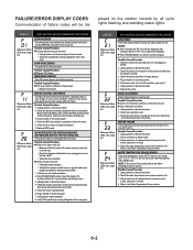
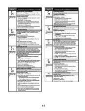
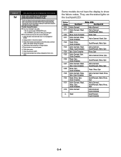
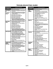
...plugged or kinked. 2. They use the status lights on the touchpad/LED. Verify CCU operation by the pressure switch during the drain or spin phases, the washer will fill 4 liters of water and during 5 minutes the unit will rest without adding any cycle....Prewash, Wash, Rinse, Spin F/33 Add a Garment Add a Garment, Cycle Complete rL Wash Soak/Prewash, Cycle Complete 6-4 Check the pressure switch. 8. Unplug washer or disconnect power. 3. DISPLAY EXPLANATION AND RECOMMENDED PROCEDURE SUDS LOCK (OVERDOSE OF DETERGENT DETECTED DURING THE WASH CYCLE) If suds are detected ...
...plugged or kinked. 2. They use the status lights on the touchpad/LED. Verify CCU operation by the pressure switch during the drain or spin phases, the washer will fill 4 liters of water and during 5 minutes the unit will rest without adding any cycle....Prewash, Wash, Rinse, Spin F/33 Add a Garment Add a Garment, Cycle Complete rL Wash Soak/Prewash, Cycle Complete 6-4 Check the pressure switch. 8. Unplug washer or disconnect power. 3. DISPLAY EXPLANATION AND RECOMMENDED PROCEDURE SUDS LOCK (OVERDOSE OF DETERGENT DETECTED DURING THE WASH CYCLE) If suds are detected ...
User Guide
Page 84
...movement at wash speed (30 sec). Drain pump Motor Motor Control (MCU) 6-6 Actuators to be Checked Door lock system Clean Washer Delicate Clean Washer Distribution system is set to CLEAN position. At the end of the cycle lights will flash and the error code will ... Distribution system is set to MW position. Dispenser motor Dispenser contact Cold water inlet valve Dispenser motor Dispenser contact Hot Water inlet valve Pressure switch: Level_wash Motor Motor Control (MCU) Heater (if equipped) Motor Motor Control (MCU) Heavy Duty Whitest Whites Heavy Duty Drain pump is...
...movement at wash speed (30 sec). Drain pump Motor Motor Control (MCU) 6-6 Actuators to be Checked Door lock system Clean Washer Delicate Clean Washer Distribution system is set to CLEAN position. At the end of the cycle lights will flash and the error code will ... Distribution system is set to MW position. Dispenser motor Dispenser contact Cold water inlet valve Dispenser motor Dispenser contact Hot Water inlet valve Pressure switch: Level_wash Motor Motor Control (MCU) Heater (if equipped) Motor Motor Control (MCU) Heavy Duty Whitest Whites Heavy Duty Drain pump is...
User Guide
Page 89
...touchpad/LED is responding. Check water connections to confirm the touchpad/LED is responding. 4. Plug in washer or reconnect power. 7. Check operating pressure switch. 7. Check operating pressure switch. 5. Verify flowmeter operation by running a Diagnostic Test or any cycle. 1. Check the MCU ...going to confirm the touchpad/LED is plugged in water source. 4. Plug in washer or reconnect power. 6. Plug in washer or reconnect power. 7. Check pressure switch hose. 6. Plug in washer or reconnect power. 7. Check drive motor. 3. Check the touchpad/LED assembly by...
...touchpad/LED is responding. Check water connections to confirm the touchpad/LED is responding. 4. Plug in washer or reconnect power. 7. Check operating pressure switch. 7. Check operating pressure switch. 5. Verify flowmeter operation by running a Diagnostic Test or any cycle. 1. Check the MCU ...going to confirm the touchpad/LED is plugged in water source. 4. Plug in washer or reconnect power. 6. Plug in washer or reconnect power. 7. Check pressure switch hose. 6. Plug in washer or reconnect power. 7. Check drive motor. 3. Check the touchpad/LED assembly by...
User Guide
Page 91
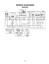
WIRING DIAGRAMS WASHER N L IF DOOR LOCK/SWITCH DS DLS Lock Unlock IF2 DS2 DL3 DLS2 1 2 12 1 2 3 1 2 DRIVE MOTOR MOTOR CONTROL UNIT (MCU) L2 N1 MS2 1 2 MI3 1 2 3 HEATING ELEMENT DRAIN PUMP INLET VALVES DISPENSER Motor Switch VC VH HE2 21 DP2 1 2 VH7 1 3 DI6 571 3 56 DR1 K1 L1 L2 K2 N1 HR2 HR1 CENTRAL CONTROL UNIT (CCU) 12 34 5 6 7 8 UI8 TOUCHPAD/LED ASSEMBLY 6 5 34 PR6 22 24 26 21 2 1 11 14 p> p> L_0 L_wash L_overflow L_sud PRESSURE SWITCH 1 2 TH2 TEMPERATURE SENSOR 7-1
WIRING DIAGRAMS WASHER N L IF DOOR LOCK/SWITCH DS DLS Lock Unlock IF2 DS2 DL3 DLS2 1 2 12 1 2 3 1 2 DRIVE MOTOR MOTOR CONTROL UNIT (MCU) L2 N1 MS2 1 2 MI3 1 2 3 HEATING ELEMENT DRAIN PUMP INLET VALVES DISPENSER Motor Switch VC VH HE2 21 DP2 1 2 VH7 1 3 DI6 571 3 56 DR1 K1 L1 L2 K2 N1 HR2 HR1 CENTRAL CONTROL UNIT (CCU) 12 34 5 6 7 8 UI8 TOUCHPAD/LED ASSEMBLY 6 5 34 PR6 22 24 26 21 2 1 11 14 p> p> L_0 L_wash L_overflow L_sud PRESSURE SWITCH 1 2 TH2 TEMPERATURE SENSOR 7-1


