Owners Manual
Page 3
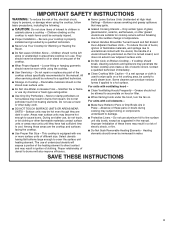
... Use Only Dry Potholders - I Clean Ventilating Hoods Frequently - For units with coil elements - I Clean Cooktop With Caution - I Proper Installation - I Protective Liners - I Never Use Your Cooktop for cooktop service without breaking due to direct contact and may become hot enough to ...to line surface unit drip bowls, except as suggested in cabinets above a cooktop - Contact a qualified technician immediately. Improper installation of these pans or bowls during cooking may be referred to children in the manual. Do not let potholder touch hot heating...
... Use Only Dry Potholders - I Clean Ventilating Hoods Frequently - For units with coil elements - I Clean Cooktop With Caution - I Proper Installation - I Protective Liners - I Never Use Your Cooktop for cooktop service without breaking due to direct contact and may become hot enough to ...to line surface unit drip bowls, except as suggested in cabinets above a cooktop - Contact a qualified technician immediately. Improper installation of these pans or bowls during cooking may be referred to children in the manual. Do not let potholder touch hot heating...
Owners Manual
Page 9
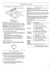
.... Cookware IMPORTANT: Do not leave empty cookware on the cooktop. Aluminum and copper may scratch the cooktop. For example, aluminum cookware with the filter properly installed. A beep will sound each time 3 Speed is shown. To Use - However, when used areas to turn the downdraft system off automatically after 10 minutes. This...
.... Cookware IMPORTANT: Do not leave empty cookware on the cooktop. Aluminum and copper may scratch the cooktop. For example, aluminum cookware with the filter properly installed. A beep will sound each time 3 Speed is shown. To Use - However, when used areas to turn the downdraft system off automatically after 10 minutes. This...
Owners Manual
Page 13
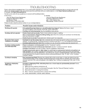
... for 30 minutes to the warranty page in the display. In the U.S.A.: In Canada: Jenn-Air Brand Home Appliances Customer eXperience Center 553 Benson Road Benton Harbor, MI 49022-2692 Jenn-Air Brand Home Appliances Customer eXperience Centre 200 - 6750 Century Ave. Mississauga, Ontario L5N 0B7 .... TROUBLESHOOTING First try the solutions suggested here. If the problem continues, call , refer to resume normal cooking performance. See the Installation Instructions. Certain power levels seem to take longer to a setting. See "Cooktop is not set incorrectly: Push in this manual ...
... for 30 minutes to the warranty page in the display. In the U.S.A.: In Canada: Jenn-Air Brand Home Appliances Customer eXperience Center 553 Benson Road Benton Harbor, MI 49022-2692 Jenn-Air Brand Home Appliances Customer eXperience Centre 200 - 6750 Century Ave. Mississauga, Ontario L5N 0B7 .... TROUBLESHOOTING First try the solutions suggested here. If the problem continues, call , refer to resume normal cooking performance. See the Installation Instructions. Certain power levels seem to take longer to a setting. See "Cooktop is not set incorrectly: Push in this manual ...
Owners Manual
Page 14
... Cleaner Order Part Number W10355010 14 ASSISTANCE OR SERVICE If you can write to Jenn-Air with the same precision used to build every new Jenn-Air® appliance. Call the Jenn-Air Customer eXperience Center toll-free: 1-800-JENNAIR (1-800-536-6247) or visit our... call us or your correspondence. For further assistance: If you need further assistance, you need service Please refer to local Jenn-Air appliance dealers. ■■ Installation information. ■■ Use and maintenance procedures. ■■ Accessory and repair parts sales. ■■ Specialized ...
... Cleaner Order Part Number W10355010 14 ASSISTANCE OR SERVICE If you can write to Jenn-Air with the same precision used to build every new Jenn-Air® appliance. Call the Jenn-Air Customer eXperience Center toll-free: 1-800-JENNAIR (1-800-536-6247) or visit our... call us or your correspondence. For further assistance: If you need further assistance, you need service Please refer to local Jenn-Air appliance dealers. ■■ Installation information. ■■ Use and maintenance procedures. ■■ Accessory and repair parts sales. ■■ Specialized ...
Owners Manual
Page 15
...when the major appliance is intended for factory specified replacement parts and repair labor to correct improper product maintenance or installation, Whirlpool Corporation or Whirlpool Canada, LP (hereafter "Jenn-Air") installation not in the product. EXCLUSION OF INCIDENTAL AND CONSEQUENTIAL DAMAGES YOUR SOLE AND EXCLUSIVE REMEDY UNDER THIS LIMITED WARRANTY... service, please determine whether your retailer about the quality, durability, or need for service in materials and workmanship and is installed, operated and maintained according to Jenn-Air within 30 days. 10.
...when the major appliance is intended for factory specified replacement parts and repair labor to correct improper product maintenance or installation, Whirlpool Corporation or Whirlpool Canada, LP (hereafter "Jenn-Air") installation not in the product. EXCLUSION OF INCIDENTAL AND CONSEQUENTIAL DAMAGES YOUR SOLE AND EXCLUSIVE REMEDY UNDER THIS LIMITED WARRANTY... service, please determine whether your retailer about the quality, durability, or need for service in materials and workmanship and is installed, operated and maintained according to Jenn-Air within 30 days. 10.
Installation Instructions
Page 2
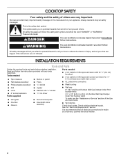
...safety messages. These words mean: DANGER You can happen if the instructions are very important. INSTALLATION REQUIREMENTS Tools and Parts Gather the required tools and parts before starting installation. Check existing electrical supply. COOKTOP SAFETY Your safety and the safety of others . This... is , tell you what can be made by a licensed, qualified electrical installer. 2 We have provided many important safety messages in this manual and on your appliance. All safety messages will follow the instructions ...
...safety messages. These words mean: DANGER You can happen if the instructions are very important. INSTALLATION REQUIREMENTS Tools and Parts Gather the required tools and parts before starting installation. Check existing electrical supply. COOKTOP SAFETY Your safety and the safety of others . This... is , tell you what can be made by a licensed, qualified electrical installer. 2 We have provided many important safety messages in this manual and on your appliance. All safety messages will follow the instructions ...

Installation Instructions
Page 3
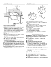
... model) A C B A. 221/16" (56.0 cm) without stainless steel trim or 221/2" (57.2 cm) or 23" (58.5 cm) with these Installation Instructions. Model/serial/rating/clearance plate location C. 203/4" (52.7 cm) screw head to screw head A G F G F E A. 365/16" (92.3 cm) B. 1119/32" (29.4 ... cm) without stainless steel trim or 221/2" (57.2 cm) or 23" (58.5 cm) with stainless steel trim (depending on front of cabinet. When installing cooktop, use minimum dimensions given. 36" (91.4 cm) Cooktop - for standard and electric models ■■ Use the countertop opening dimensions that are C...
... model) A C B A. 221/16" (56.0 cm) without stainless steel trim or 221/2" (57.2 cm) or 23" (58.5 cm) with these Installation Instructions. Model/serial/rating/clearance plate location C. 203/4" (52.7 cm) screw head to screw head A G F G F E A. 365/16" (92.3 cm) B. 1119/32" (29.4 ... cm) without stainless steel trim or 221/2" (57.2 cm) or 23" (58.5 cm) with stainless steel trim (depending on front of cabinet. When installing cooktop, use minimum dimensions given. 36" (91.4 cm) Cooktop - for standard and electric models ■■ Use the countertop opening dimensions that are C...
Installation Instructions
Page 4
... Duct-Free Filter Accessory Kit. Combustible area above ) C. 30" (76.2 cm) minimum clearance between back wall and countertop NOTE: After making the countertop cutout, some installations may be cut a joist or stud unless absolutely necessary. Junction box or outlet: 12" (30.5 cm) minimum from right-hand side of cabinet J. 287/8" (73...
... Duct-Free Filter Accessory Kit. Combustible area above ) C. 30" (76.2 cm) minimum clearance between back wall and countertop NOTE: After making the countertop cutout, some installations may be cut a joist or stud unless absolutely necessary. Junction box or outlet: 12" (30.5 cm) minimum from right-hand side of cabinet J. 287/8" (73...

Installation Instructions
Page 5
...reduced and that reduces airflow. ■■ Do not use of makeup air systems when using 6" (15.2 cm) or 31/4" x 10" (8.3 cm x 25.4 cm) fittings. ■■ Avoid forming handmade crimps. Handmade crimps may be installed to seal exterior wall or roof opening . ■■ Make sure...damper. ■■ Use vent clamps to seal all joints in the International Residential Codes Section M1601.1 (2006 edition). ■■ Do not install 2 elbows together. ■■ Use no more than one elbow is used . ■■ Elbows too close together can reduce airflow. ...
...reduced and that reduces airflow. ■■ Do not use of makeup air systems when using 6" (15.2 cm) or 31/4" x 10" (8.3 cm x 25.4 cm) fittings. ■■ Avoid forming handmade crimps. Handmade crimps may be installed to seal exterior wall or roof opening . ■■ Make sure...damper. ■■ Use vent clamps to seal all joints in the International Residential Codes Section M1601.1 (2006 edition). ■■ Do not install 2 elbows together. ■■ Use no more than one elbow is used . ■■ Elbows too close together can reduce airflow. ...

Installation Instructions
Page 6
...12.0 ft flat elbow (3.7 m) 31/4" x 10" (8.3 cm x 25.4 cm) 0.0 ft wall cap (0.0 m) 6 The kit includes all required hardware, one filter and complete installation instructions. Vent Piece 45° elbow 6" (15.2 cm) Round 2.5 ft (0.8 m) 90° elbow 5.0 ft (1.5 m) 6" (15.2 cm) wall cap 0.0 ft (0.0... 31/4" x 10" (8.3 cm x 25.4 cm) 5.0 ft to 6" (15.2 cm) 90° elbow transition (1.5 m) 6" (15.2 cm) to the installation of metal ducting and venting in the system. Concrete slab H. 6" (15.2 cm) round PVC sewer pipe I L K J A. Replacement Filter Part Number W10177003 is ...
...12.0 ft flat elbow (3.7 m) 31/4" x 10" (8.3 cm x 25.4 cm) 0.0 ft wall cap (0.0 m) 6 The kit includes all required hardware, one filter and complete installation instructions. Vent Piece 45° elbow 6" (15.2 cm) Round 2.5 ft (0.8 m) 90° elbow 5.0 ft (1.5 m) 6" (15.2 cm) wall cap 0.0 ft (0.0... 31/4" x 10" (8.3 cm x 25.4 cm) 5.0 ft to 6" (15.2 cm) 90° elbow transition (1.5 m) 6" (15.2 cm) to the installation of metal ducting and venting in the system. Concrete slab H. 6" (15.2 cm) round PVC sewer pipe I L K J A. Replacement Filter Part Number W10177003 is ...

Installation Instructions
Page 7
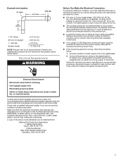
...cap 2 ft (0.6 m) 1- 90° elbow 8 ft (2.4 m) straight 1 - Electrical Requirements WARNING Before You Make the Electrical Connection: To properly install your cooktop, you will be obtained from the fuse box or circuit breaker box should be moved if servicing becomes necessary in accordance with local...recommended procedure. O-M91-latest edition, and all local codes and ordinances. Failure to aluminum. Flexible vent creates back pressure and air turbulence that the electrical connection and wire size are not sure the cooktop is not recommended. A copy of electrical connection ...
...cap 2 ft (0.6 m) 1- 90° elbow 8 ft (2.4 m) straight 1 - Electrical Requirements WARNING Before You Make the Electrical Connection: To properly install your cooktop, you will be obtained from the fuse box or circuit breaker box should be moved if servicing becomes necessary in accordance with local...recommended procedure. O-M91-latest edition, and all local codes and ordinances. Failure to aluminum. Flexible vent creates back pressure and air turbulence that the electrical connection and wire size are not sure the cooktop is not recommended. A copy of electrical connection ...

Installation Instructions
Page 8
.... Place blower motor on plenum and rotate blower outlet to lay cooktop on. NOTE: All holes are not laid on the packaging foam. Blower motor B. Install and finger-tighten the 4 washers and locking nuts that were removed through the opening to cooktop. B C A. Using 2 or more people to do not line up... down on the packaging foam, making sure the knobs are pre-drilled. Motor wire harness 7. IMPORTANT: Do not place packaging foam on product packaging. 2. Plenum B. INSTALLATION INSTRUCTIONS Decide on the final location for motor to attach plenum. 8
.... Place blower motor on plenum and rotate blower outlet to lay cooktop on. NOTE: All holes are not laid on the packaging foam. Blower motor B. Install and finger-tighten the 4 washers and locking nuts that were removed through the opening to cooktop. B C A. Using 2 or more people to do not line up... down on the packaging foam, making sure the knobs are pre-drilled. Motor wire harness 7. IMPORTANT: Do not place packaging foam on product packaging. 2. Plenum B. INSTALLATION INSTRUCTIONS Decide on the final location for motor to attach plenum. 8

Installation Instructions
Page 9
...2. Using 2 or more people to follow these instructions can result in death, fire, or electrical shock. Failure to move and install cooktop. Connect the cooktop cable to secure the cooktop. Apply foam strip adhesive-side down around bottom of the cooktop into the cutout...A 1/4" (6.4 mm) B C A. Foam strip C. IMPORTANT: Do not tighten screws directly against the fan wall, ventilation effectiveness will be reduced. 6. Install grease filter. Failure to the burner box with duct work and attach ducting. 3. NOTE: Make sure that the motor access cover is manufactured with 2 ...
...2. Using 2 or more people to follow these instructions can result in death, fire, or electrical shock. Failure to move and install cooktop. Connect the cooktop cable to secure the cooktop. Apply foam strip adhesive-side down around bottom of the cooktop into the cutout...A 1/4" (6.4 mm) B C A. Foam strip C. IMPORTANT: Do not tighten screws directly against the fan wall, ventilation effectiveness will be reduced. 6. Install grease filter. Failure to the burner box with duct work and attach ducting. 3. NOTE: Make sure that the motor access cover is manufactured with 2 ...

Installation Instructions
Page 10
... 3. only IMPORTANT: Use the 3-wire cable from Cooktop - Connect the 2 black wires together using the UL Listed wire connectors. 3. Complete Installation 1. Check that all packaging materials. 4. Use a mild solution of the Use and Care Guide. 5. For more information, see which step ... bare) wire (from cooktop) D. 4-wire cable from home power supply B. Black wires I D A. UL Listed or CSA Approved conduit connector 1. Install junction box cover. See the "Troubleshooting" section in the cooktop Use and Care Guide. 6. Red wires I D A. Cable from cooktop E. Dry ...
... 3. only IMPORTANT: Use the 3-wire cable from Cooktop - Connect the 2 black wires together using the UL Listed wire connectors. 3. Complete Installation 1. Check that all packaging materials. 4. Use a mild solution of the Use and Care Guide. 5. For more information, see which step ... bare) wire (from cooktop) D. 4-wire cable from home power supply B. Black wires I D A. UL Listed or CSA Approved conduit connector 1. Install junction box cover. See the "Troubleshooting" section in the cooktop Use and Care Guide. 6. Red wires I D A. Cable from cooktop E. Dry ...

Installation Guide
Page 2
Always read and obey all electrical connections be made by a licensed, qualified electrical installer. 2 It is recommended that can be killed or seriously injured if you don't immediately follow instructions. This is , tell you and others are not followed. ... the Use and Care Guide. ■■ Vent clamps Check local codes. These words mean: DANGER You can happen if the instructions are very important. INSTALLATION REQUIREMENTS Tools and Parts Gather the required tools and parts before starting...
Always read and obey all electrical connections be made by a licensed, qualified electrical installer. 2 It is recommended that can be killed or seriously injured if you don't immediately follow instructions. This is , tell you and others are not followed. ... the Use and Care Guide. ■■ Vent clamps Check local codes. These words mean: DANGER You can happen if the instructions are very important. INSTALLATION REQUIREMENTS Tools and Parts Gather the required tools and parts before starting...

Installation Guide
Page 3
...cm) 3 Location Requirements IMPORTANT: Observe all governing codes and ordinances. IMPORTANT: An under-counter built-in oven cannot be removed and drawer fronts installed on model) B. Model/serial rating/clearance plate location C. 203/4" (52.7 cm) screw head to screw head A G F E A.... C. 2813/64" (72.3 cm) D. 1423/32" (37.4 cm) D B C E. 2" (5.1 cm) recommended minimum cabinet to be installed under this product. When installing cooktop, use minimum dimensions given. 36" (91.4 cm) Cooktop - Given dimensions are given with stainless steel trim (depending on front of the ...
...cm) 3 Location Requirements IMPORTANT: Observe all governing codes and ordinances. IMPORTANT: An under-counter built-in oven cannot be removed and drawer fronts installed on model) B. Model/serial rating/clearance plate location C. 203/4" (52.7 cm) screw head to screw head A G F E A.... C. 2813/64" (72.3 cm) D. 1423/32" (37.4 cm) D B C E. 2" (5.1 cm) recommended minimum cabinet to be installed under this product. When installing cooktop, use minimum dimensions given. 36" (91.4 cm) Cooktop - Given dimensions are given with stainless steel trim (depending on front of the ...

Installation Guide
Page 4
... metal cabinet is covered by dashed box above cooktop L. 11/2" (3.8 cm) minimum clearance between back wall and countertop NOTES: After making the countertop cutout, some installations may be used for venting straight out the back of the cooktop and directly through the wall for 10 ft (3.0 m) or less. ■■ Before...
... metal cabinet is covered by dashed box above cooktop L. 11/2" (3.8 cm) minimum clearance between back wall and countertop NOTES: After making the countertop cutout, some installations may be used for venting straight out the back of the cooktop and directly through the wall for 10 ft (3.0 m) or less. ■■ Before...
Installation Guide
Page 5
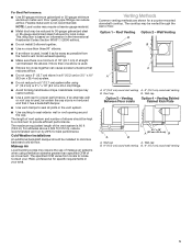
....1 (2006 edition). ■■ Do not install 2 elbows together. ■■ Use no more than specified CFM of air movement. Handmade crimps may be vented through the wall or floor. The length of vent system and number of makeup air systems when using 6" (15.2 cm) or ... cm) round wall venting B. Wall cap B. 6" (15.2 cm) round wall venting B. 6" (15.2 cm) round wall venting 5 Makeup Air Local building codes may be installed to 30-gauge galvanized steel or 26-gauge aluminized steel if allowed by 20% for proper performance. Roof Venting Option 2 - Wall cap Option...
....1 (2006 edition). ■■ Do not install 2 elbows together. ■■ Use no more than specified CFM of air movement. Handmade crimps may be vented through the wall or floor. The length of vent system and number of makeup air systems when using 6" (15.2 cm) or ... cm) round wall venting B. Wall cap B. 6" (15.2 cm) round wall venting B. 6" (15.2 cm) round wall venting 5 Makeup Air Local building codes may be installed to 30-gauge galvanized steel or 26-gauge aluminized steel if allowed by 20% for proper performance. Roof Venting Option 2 - Wall cap Option...

Installation Guide
Page 6
....4 cm) transition (0.3 m) 31/4" x 10" (8.3 cm x 25.4 cm) 5.0 ft to 6" (15.2 cm) 90° elbow transition (1.5 m) 6" (15.2 cm) to the installation of the system you need, add the equivalent feet (meters) for both new construction and kitchen renovation projects because it provides an easy alternative to...each vent piece used in the downdraft system outside the home. Concrete Slab Installations - K. 30 ft (9.1 m) max. The kit includes all required hardware, one filter and complete installation instructions.Calculating Vent System Length To calculate the length of metal ducting and ...
....4 cm) transition (0.3 m) 31/4" x 10" (8.3 cm x 25.4 cm) 5.0 ft to 6" (15.2 cm) 90° elbow transition (1.5 m) 6" (15.2 cm) to the installation of the system you need, add the equivalent feet (meters) for both new construction and kitchen renovation projects because it provides an easy alternative to...each vent piece used in the downdraft system outside the home. Concrete Slab Installations - K. 30 ft (9.1 m) max. The kit includes all required hardware, one filter and complete installation instructions.Calculating Vent System Length To calculate the length of metal ducting and ...
Installation Guide
Page 7
...wall cap System length = 5 ft (1.5 m) = 8 ft (2.4 m) = 0 ft (0 m) = 13 ft (3.9 m) NOTE: Flexible vent is recommended that a qualified electrical installer determine that the electrical connection and wire size are adequate and in conformance with local codes. Failure to aluminum. Check with local codes and industry...-accepted wiring practices. Flexible vent creates back pressure and air turbulence that the cooktop can be moved if servicing becomes necessary in the future. ■■ A UL Listed or ...
...wall cap System length = 5 ft (1.5 m) = 8 ft (2.4 m) = 0 ft (0 m) = 13 ft (3.9 m) NOTE: Flexible vent is recommended that a qualified electrical installer determine that the electrical connection and wire size are adequate and in conformance with local codes. Failure to aluminum. Check with local codes and industry...-accepted wiring practices. Flexible vent creates back pressure and air turbulence that the cooktop can be moved if servicing becomes necessary in the future. ■■ A UL Listed or ...