

Owners Manual
Page 11
... Crutch Holder, Drafting Bumper, Indoor Training Roller Computer, Tow Bar, Safety Lights, Helmet, Flag, Bike Rack, Water Bottle and Cage, Fixed seat frame, Alignment Gauge, Backpack Hydration System, Carbon Fiber Wheels, Crutch Holder, Drafting Bumper, Titanium Parts, Indoor Training Roller *NOTE: Knobby tires will reduce side... Rapid fire hands-on shifter mounted on right Rapid fire hands-on shifter mounted on pedal. TYPICAL PRODUCT PARAMETERS TOP END XLT PRO TOP END XLT GOLD Seat Width: 14 to 18 inches 14 to 18 inches Seat Depth: 15 inches 15 inches Seat-to approximately 1&#...
... Crutch Holder, Drafting Bumper, Indoor Training Roller Computer, Tow Bar, Safety Lights, Helmet, Flag, Bike Rack, Water Bottle and Cage, Fixed seat frame, Alignment Gauge, Backpack Hydration System, Carbon Fiber Wheels, Crutch Holder, Drafting Bumper, Titanium Parts, Indoor Training Roller *NOTE: Knobby tires will reduce side... Rapid fire hands-on shifter mounted on right Rapid fire hands-on shifter mounted on pedal. TYPICAL PRODUCT PARAMETERS TOP END XLT PRO TOP END XLT GOLD Seat Width: 14 to 18 inches 14 to 18 inches Seat Depth: 15 inches 15 inches Seat-to approximately 1&#...
Owners Manual
Page 13
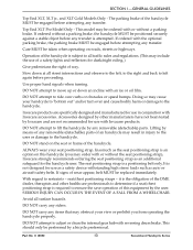
...XLT, XLT jr., and XLT Gold Models Only ‐ The parking brake of the handcycle. Slow down an incline with an ice or oil film. DO NOT attempt to left , to the right and back to lift the handcycle by any removable (detachable) parts. DO NOT stand on the seat or frame...Operation of the handcycle is an option on roads, streets or highways. DO NOT attempt to the handcycle. Invacare products are not recommended for the handcycle user. Lifting by Invacare and are specifically designed and manufactured for dusk/night riding.) Give pedestrians the right of wear appear, belt ...
...XLT, XLT jr., and XLT Gold Models Only ‐ The parking brake of the handcycle. Slow down an incline with an ice or oil film. DO NOT attempt to left , to the right and back to lift the handcycle by any removable (detachable) parts. DO NOT stand on the seat or frame...Operation of the handcycle is an option on roads, streets or highways. DO NOT attempt to the handcycle. Invacare products are not recommended for the handcycle user. Lifting by Invacare and are specifically designed and manufactured for dusk/night riding.) Give pedestrians the right of wear appear, belt ...
Owners Manual
Page 17
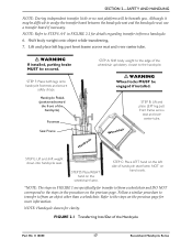
... Wheel locks MUST be difficult to the steps in the procedure on the previous page for clarity. Footrest Seat Frame STEP A: Shift body weight to the edge of handcycle seat frame, NOT on hand crank. *NOTE: The steps in FIGURE 2.1 for transfer to the steps on the previous... weight onto object while transferring. 7. FIGURE 2.1 Transferring Into/Out of the handcycle). Handcycle Wheelchair STEP B: Lift and place LEFT leg past front frame across seat and over center tube. ƽ WARNING If installed, parking brake MUST be beneath you. STEP C: Place LEFT hand on the wheelchair...
... Wheel locks MUST be difficult to the steps in the procedure on the previous page for clarity. Footrest Seat Frame STEP A: Shift body weight to the edge of handcycle seat frame, NOT on hand crank. *NOTE: The steps in FIGURE 2.1 for transfer to the steps on the previous... weight onto object while transferring. 7. FIGURE 2.1 Transferring Into/Out of the handcycle). Handcycle Wheelchair STEP B: Lift and place LEFT leg past front frame across seat and over center tube. ƽ WARNING If installed, parking brake MUST be beneath you. STEP C: Place LEFT hand on the wheelchair...
Owners Manual
Page 18
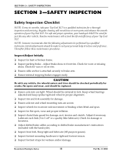
... and efficiency of your personal body structure and preference. NOTE: Invacare recommends that the following adjustments be cared for just like any ... Ensure axle nut and wheel mounting nuts are tight. For safe and proper operation, your Top End XLT to a qualified technician for wetness and/or damage. Check for wax or oil on rim. ❑... inspection and servicing. CAUTION As with the handcycle). ❑ Inspect front fork. Check for bent or broken frame. ❑ Inspect parking brake ‐ Adjust brake shoes to shifter/brake manufacturerʹs instructions (included with ...
... and efficiency of your personal body structure and preference. NOTE: Invacare recommends that the following adjustments be cared for just like any ... Ensure axle nut and wheel mounting nuts are tight. For safe and proper operation, your Top End XLT to a qualified technician for wetness and/or damage. Check for wax or oil on rim. ❑... inspection and servicing. CAUTION As with the handcycle). ❑ Inspect front fork. Check for bent or broken frame. ❑ Inspect parking brake ‐ Adjust brake shoes to shifter/brake manufacturerʹs instructions (included with ...
Owners Manual
Page 19
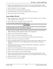
...; Adjust brake shoes to brake arm. ❑ Ensure internal stopping brakes engages easily. Check for damage or looseness. ❑ Adjust shifter/brake cables according to frame is tight and footrest secure. ❑ Inspect footrest straps for wetness and/or damage. ❑ Inspect seat positioning strap for any vehicle, the wheels/casters... of wear. Lubricate each link (3‐in‐1 oil or a quality bike lubricant). Check for worn or missing shoes. Verify hardware that attaches strap to frame is attached securely to front rim.
...; Adjust brake shoes to brake arm. ❑ Ensure internal stopping brakes engages easily. Check for damage or looseness. ❑ Adjust shifter/brake cables according to frame is tight and footrest secure. ❑ Inspect footrest straps for wetness and/or damage. ❑ Inspect seat positioning strap for any vehicle, the wheels/casters... of wear. Lubricate each link (3‐in‐1 oil or a quality bike lubricant). Check for worn or missing shoes. Verify hardware that attaches strap to frame is attached securely to front rim.
Owners Manual
Page 20
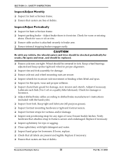
...Verify hardware that attaches strap to front rim. Inspect/Adjust Periodically ❑ Inspect for bent or broken frame. ❑ Inspect parking brake ‐ Adjust brake shoes to frame is tight and footrest secure. ❑ Inspect footrest straps for wetness and/or damage. ❑ ... quality bike lubricant). Recumbent Handcycle Series 20 Part No 1114850 SECTION 3-SAFETY INSPECTION Inspect/Adjust Monthly ❑ Inspect for bent or broken frame. ❑ Ensure that casters are free of debris. CAUTION As with light detergent and water. ❑ Inspect hand grips for worn...
...Verify hardware that attaches strap to front rim. Inspect/Adjust Periodically ❑ Inspect for bent or broken frame. ❑ Inspect parking brake ‐ Adjust brake shoes to frame is tight and footrest secure. ❑ Inspect footrest straps for wetness and/or damage. ❑ ... quality bike lubricant). Recumbent Handcycle Series 20 Part No 1114850 SECTION 3-SAFETY INSPECTION Inspect/Adjust Monthly ❑ Inspect for bent or broken frame. ❑ Ensure that casters are free of debris. CAUTION As with light detergent and water. ❑ Inspect hand grips for worn...
Owners Manual
Page 21
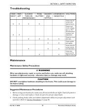
...for loose X X X X axle nuts. Refer to the frame. Check spokes X X and nipples. X X tings are tight. Check parking brake cable and shifter adjustment cables for proper adjustment. 2. X X Check road crown compensator or XLT Gold dampener hardware and adjustment Check for damage or wear and ...replace. Part No 1114850 21 Recumbent Handcycle Series otherwise injury or damage may result. This could cause damage to the frame tubing. Check all parts for proper ...
...for loose X X X X axle nuts. Refer to the frame. Check spokes X X and nipples. X X tings are tight. Check parking brake cable and shifter adjustment cables for proper adjustment. 2. X X Check road crown compensator or XLT Gold dampener hardware and adjustment Check for damage or wear and ...replace. Part No 1114850 21 Recumbent Handcycle Series otherwise injury or damage may result. This could cause damage to the frame tubing. Check all parts for proper ...
Owners Manual
Page 24
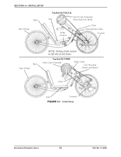
Top End XLT PRO Hand Crank Assembly Brake Cable Fork Mounted Shifters and Brakes Chain Seat Footrest FIGURE 4.1 Initial Setup Recumbent Handcycle Series 24 Part No 1114850 SECTION 4-INITIAL SETUP Back Rear Wheel Top End XLT/XLT Jr. Hand Crank Assembly/ Seat Reversing Drum Brake Shifter Location Chain Parking Brake Cable Footrest Back Rear Wheel NOTE: Parking brake located on left side of seat frame.
Top End XLT PRO Hand Crank Assembly Brake Cable Fork Mounted Shifters and Brakes Chain Seat Footrest FIGURE 4.1 Initial Setup Recumbent Handcycle Series 24 Part No 1114850 SECTION 4-INITIAL SETUP Back Rear Wheel Top End XLT/XLT Jr. Hand Crank Assembly/ Seat Reversing Drum Brake Shifter Location Chain Parking Brake Cable Footrest Back Rear Wheel NOTE: Parking brake located on left side of seat frame.

Owners Manual
Page 31
... button. Parking Brake Location Slots or Hook and Loop Strap (Not Shown) Handle NOTE: Approximate location shown. Actual side of handcycle and location on seat frame may vary. Hands should be done while rotating the hand crank (pedaling) or coasting. • When cornering, it is recommended that you slow the handcycle...
... button. Parking Brake Location Slots or Hook and Loop Strap (Not Shown) Handle NOTE: Approximate location shown. Actual side of handcycle and location on seat frame may vary. Hands should be done while rotating the hand crank (pedaling) or coasting. • When cornering, it is recommended that you slow the handcycle...
Owners Manual
Page 36
...right and left side of the seat frame to the desired position. 6. Tighten the hex bolts and locknuts that secure the front of the handcycle. 4. All Models Except XLT Gold and Top End Force Recumbent Handcycle Series 36 Part No 1114850 All Models Except XLT Gold and Top End Force NOTE: ...For this procedure, refer to the rear seat supports securely. Loosen, but DO NOT remove the hex bolts and locknuts that secure the seat frame to the rear seat supports. Tighten the six socket...
...right and left side of the seat frame to the desired position. 6. Tighten the hex bolts and locknuts that secure the front of the handcycle. 4. All Models Except XLT Gold and Top End Force Recumbent Handcycle Series 36 Part No 1114850 All Models Except XLT Gold and Top End Force NOTE: ...For this procedure, refer to the rear seat supports securely. Loosen, but DO NOT remove the hex bolts and locknuts that secure the seat frame to the rear seat supports. Tighten the six socket...
Owners Manual
Page 38
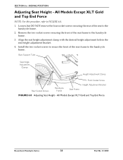
... and Top End Force NOTE: For this procedure, refer to the handcycle frame. 3. All Models Except XLT Gold and Top End Force Recumbent Handcycle Series 38 Part No 1114850 Align the seat height adjustment clamp with the desired height adjustment hole in ...the seat height adjustment bracket. 4. Remove the two socket screws securing the front of the seat frame to FIGURE 6.8. 1. Install the two socket screws...
... and Top End Force NOTE: For this procedure, refer to the handcycle frame. 3. All Models Except XLT Gold and Top End Force Recumbent Handcycle Series 38 Part No 1114850 Align the seat height adjustment clamp with the desired height adjustment hole in ...the seat height adjustment bracket. 4. Remove the two socket screws securing the front of the seat frame to FIGURE 6.8. 1. Install the two socket screws...
Owners Manual
Page 39
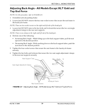
...screws that secure the two seat angle adjustment clamps to the handcycle frame securely. 6. Tighten the hex bolts and locknuts that secure the seat frame to the rear seat supports securely. All Models Except XLT Gold and Top End Force Part No 1114850 39 Recumbent Handcycle Series...support tubes, pull the seat upward to FIGURE 6.9. 1. Back Support Tube Seat Angle Adjustment Clamps Rear Socket Screws Handcycle Frame FIGURE 6.9 Adjusting Back Angle - All Models Except XLT Gold and Top End Force NOTE: For this procedure, refer to the desired position. • Decreasing Back Angle &#...
...screws that secure the two seat angle adjustment clamps to the handcycle frame securely. 6. Tighten the hex bolts and locknuts that secure the seat frame to the rear seat supports securely. All Models Except XLT Gold and Top End Force Part No 1114850 39 Recumbent Handcycle Series...support tubes, pull the seat upward to FIGURE 6.9. 1. Back Support Tube Seat Angle Adjustment Clamps Rear Socket Screws Handcycle Frame FIGURE 6.9 Adjusting Back Angle - All Models Except XLT Gold and Top End Force NOTE: For this procedure, refer to the desired position. • Decreasing Back Angle &#...

Owners Manual
Page 43
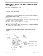
...: Invacare recommends that these suggestions may cause the tire to follow these procedures be performed by a qualified technician. Axle Mounting Hole ¼-inch Allen Wrench Frame Rear Wheel Axle FIGURE 7.2 Installing the Rear Wheels with Threaded Axles NOTE: For this procedure, refer to the frame. ...Tire p.s.i. is printed on the handcycle frame. 3. SECTION 7-WHEELS Installing the Rear Wheels with Threaded Axles Replacing Tire/Tube and Tuning/Replacement of grease onto ...
...: Invacare recommends that these suggestions may cause the tire to follow these procedures be performed by a qualified technician. Axle Mounting Hole ¼-inch Allen Wrench Frame Rear Wheel Axle FIGURE 7.2 Installing the Rear Wheels with Threaded Axles NOTE: For this procedure, refer to the frame. ...Tire p.s.i. is printed on the handcycle frame. 3. SECTION 7-WHEELS Installing the Rear Wheels with Threaded Axles Replacing Tire/Tube and Tuning/Replacement of grease onto ...

Owners Manual
Page 45
... the socket screws and clamps that secure camber inserts to Determining Toe In/Toe Out on page 44. Clamp Camber Camber Bar Insert Socket Screw Frame FIGURE 7.4 - Securely tighten the socket screws and clamps that secure the camber inserts to Determining/Adjusting Toe In/Toe Out on page 44. 5. Refer to...
... the socket screws and clamps that secure camber inserts to Determining Toe In/Toe Out on page 44. Clamp Camber Camber Bar Insert Socket Screw Frame FIGURE 7.4 - Securely tighten the socket screws and clamps that secure the camber inserts to Determining/Adjusting Toe In/Toe Out on page 44. 5. Refer to...

Owners Manual
Page 46
... secure the footrests to the brake arm clamp. 11. Slide the crank handles down towards the front wheel. 4. Remove the crank handles from the frame. Remove the socket nut on page 48. Refer to FIGURE 8.1 on the back of the crank handles. 2. Remove the two hex bolts, locknuts... nuts that secures the shifting lever to the existing fork. 13. Remove the two top nuts that secure the crank handles to the frame. 18. NOTE: Invacare recommends that secures the brake assembly. 7. Remove the front wheel from the existing fork. 12. Recumbent Handcycle Series 46 Part No 1114850...
... secure the footrests to the brake arm clamp. 11. Slide the crank handles down towards the front wheel. 4. Remove the crank handles from the frame. Remove the socket nut on page 48. Refer to FIGURE 8.1 on the back of the crank handles. 2. Remove the two hex bolts, locknuts... nuts that secures the shifting lever to the existing fork. 13. Remove the two top nuts that secure the crank handles to the frame. 18. NOTE: Invacare recommends that secures the brake assembly. 7. Remove the front wheel from the existing fork. 12. Recumbent Handcycle Series 46 Part No 1114850...

Owners Manual
Page 47
... tighten securely with the hex bolt and locknut. Slide the crank handles onto the new fork. Position the o‐ring and bearing on the new frame. 24. Refer to FIGURE 8.1 for correct orientation. 20. Install the two nuts onto the new fork and tighten securely. Position the chain around ... position noted in STEP 17 and secure with the socket screw. 33. Part No 1114850 47 Recumbent Handcycle Series Slide the new fork into the frame. 21. Install the road crown compensator or steering dampener onto the new fork. Install the brake assembly onto the new fork. Move the crank...
... tighten securely with the hex bolt and locknut. Slide the crank handles onto the new fork. Position the o‐ring and bearing on the new frame. 24. Refer to FIGURE 8.1 for correct orientation. 20. Install the two nuts onto the new fork and tighten securely. Position the chain around ... position noted in STEP 17 and secure with the socket screw. 33. Part No 1114850 47 Recumbent Handcycle Series Slide the new fork into the frame. 21. Install the road crown compensator or steering dampener onto the new fork. Install the brake assembly onto the new fork. Move the crank...

Owners Manual
Page 48
... 15, 16, 23, 24 Fork Hex Bolts, Locknuts and Footrest Clamps STEPS 5, 17, 18, 19, 20, 21, 22, 35 Top Nuts Crank Handle Bearing O-Ring Frame Frame Fork Bottom Bearing FIGURE 8.1 Replacing the Fork/Crank Assembly Recumbent Handcycle Series 48 Part No 1114850
... 15, 16, 23, 24 Fork Hex Bolts, Locknuts and Footrest Clamps STEPS 5, 17, 18, 19, 20, 21, 22, 35 Top Nuts Crank Handle Bearing O-Ring Frame Frame Fork Bottom Bearing FIGURE 8.1 Replacing the Fork/Crank Assembly Recumbent Handcycle Series 48 Part No 1114850
Owners Manual
Page 50
XLT Gold, XLT PRO and Top End Force Installing/Removing/Adjusting the Road Crown Compensator NOTE: For this procedure, refer to position the fork end onto the fork bolt. NOTE: If necessary, lengthen or shorten the road crown compensator to FIGURE 8.3 on page 51. Position the bolt through the frame... Crown Compensator 1. Secure the road crown compensator to one side or another. Rotate the fork to Adjusting Road Crown Compensator on the frame. 4. Refer to ensure the front wheel is not intended to keep the handcycle straight when pedaling but to keep the handcycle from leaning...
XLT Gold, XLT PRO and Top End Force Installing/Removing/Adjusting the Road Crown Compensator NOTE: For this procedure, refer to position the fork end onto the fork bolt. NOTE: If necessary, lengthen or shorten the road crown compensator to FIGURE 8.3 on page 51. Position the bolt through the frame... Crown Compensator 1. Secure the road crown compensator to one side or another. Rotate the fork to Adjusting Road Crown Compensator on the frame. 4. Refer to ensure the front wheel is not intended to keep the handcycle straight when pedaling but to keep the handcycle from leaning...

Owners Manual
Page 51
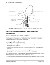
Remove the locknut securing the fork end of the road crown compensator to the frame. Remove the bolt and spacer securing the frame end of the road crown compensator to adjust the length. Counterclockwise ‐ lengthens the road crown compensator and ...compensator from the fork bolt. 3. Adjustment Fork End Road Crown Compensator Fork Bolt Removed Locknut Installed Frame Frame Frame Mounting Hole Fork End Fork Road Crown Compensator Road Crown Compensator Frame End Bolt Spacer FIGURE 8.3 Installing/Removing/Adjusting the Road Crown Compensator Part No 1114850 51 Recumbent ...
Remove the locknut securing the fork end of the road crown compensator to the frame. Remove the bolt and spacer securing the frame end of the road crown compensator to adjust the length. Counterclockwise ‐ lengthens the road crown compensator and ...compensator from the fork bolt. 3. Adjustment Fork End Road Crown Compensator Fork Bolt Removed Locknut Installed Frame Frame Frame Mounting Hole Fork End Fork Road Crown Compensator Road Crown Compensator Frame End Bolt Spacer FIGURE 8.3 Installing/Removing/Adjusting the Road Crown Compensator Part No 1114850 51 Recumbent ...

Owners Manual
Page 52
...8.4 on page 52. Test drive handcycle, if handcycle pulls to the handcycle frame. 2. Recumbent Handcycle Series 52 Part No 1114850 SECTION 8-SERVICE PROCEDURES Installing/Removing/Adjusting the Steering Dampener For Top End XLT Gold and Force Only NOTE: For this procedure, refer to the dampener clamp... securing the dampener clamp to the crank assembly tab. 5. Using two socket screws, loosely secure the dampener clamp to the handcycle frame. 3. Remove the locknut securing the upper threaded post of the steering dampener 4. While inserting the lower threaded post into the tab...
...8.4 on page 52. Test drive handcycle, if handcycle pulls to the handcycle frame. 2. Recumbent Handcycle Series 52 Part No 1114850 SECTION 8-SERVICE PROCEDURES Installing/Removing/Adjusting the Steering Dampener For Top End XLT Gold and Force Only NOTE: For this procedure, refer to the dampener clamp... securing the dampener clamp to the crank assembly tab. 5. Using two socket screws, loosely secure the dampener clamp to the handcycle frame. 3. Remove the locknut securing the upper threaded post of the steering dampener 4. While inserting the lower threaded post into the tab...
