
Owners Manual 4
Page 24
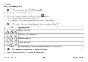
.... The three icons indicate up/down, up or down, respectively. 5. Select the desired operation using the joystick or an equivalent switch. Make sure the wheelchair is selected: The location of the icons indicates the joystick direction or quadrant (Detail "B"). ICON DESCRIPTION Elevate Operations Combined Power Leg Operations Right Leg... displayed. 3. Select the Actuator Control Switch Mode icon (Detail "A"). 4. Four of the following icons will display when Actuator Control Switch Mode is on page 25. 1. Invacare® Van Seat 24 Part No 1143195
.... The three icons indicate up/down, up or down, respectively. 5. Select the desired operation using the joystick or an equivalent switch. Make sure the wheelchair is selected: The location of the icons indicates the joystick direction or quadrant (Detail "B"). ICON DESCRIPTION Elevate Operations Combined Power Leg Operations Right Leg... displayed. 3. Select the Actuator Control Switch Mode icon (Detail "A"). 4. Four of the following icons will display when Actuator Control Switch Mode is on page 25. 1. Invacare® Van Seat 24 Part No 1143195

Owners Manual 2
Page 3
Forward ...24 Reaching, Bending - Backward ...25 Transferring To and From Other Seats...26 Storage...27 Electrical - CONTENTS 1 GENERAL ...8 Symbols ...8 Warnings...8 Reference Documents ...9 Global Limited Warranty (... ...13 Setup ...13 Transport...14 Repair or Service Information ...16 Safety/Handling ...17 A Note to Wheelchair Assistants...19 Stability and Balance ...20 Coping with Everyday Obstacles...22 Pinch Points...23 Footplates and Front Rigging...24 Reaching, Leaning and Bending - Batteries ...28 Electrical - Grounding Instructions...28 Electrical - Charging Batteries...29 ...
Forward ...24 Reaching, Bending - Backward ...25 Transferring To and From Other Seats...26 Storage...27 Electrical - CONTENTS 1 GENERAL ...8 Symbols ...8 Warnings...8 Reference Documents ...9 Global Limited Warranty (... ...13 Setup ...13 Transport...14 Repair or Service Information ...16 Safety/Handling ...17 A Note to Wheelchair Assistants...19 Stability and Balance ...20 Coping with Everyday Obstacles...22 Pinch Points...23 Footplates and Front Rigging...24 Reaching, Leaning and Bending - Batteries ...28 Electrical - Grounding Instructions...28 Electrical - Charging Batteries...29 ...
Owners Manual 2
Page 24
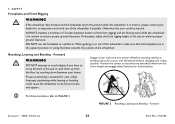
...turn power off before reaching, leaning or bending only as far as a platform. Otherwise the user could cause the wheelchair to FIGURE 3. ALWAYS maintain a minimum of 3-inches between your knees. If necessary, adjust the front rigging height ... move forward in the upward position or swing footrests towards the outside of the wheelchair. When getting in or out of the wheelchair, make sure that they are in the seat or pick them up from the...NOT attempt to reach objects if you have to achieve proper ground clearance. Forward Invacare® TDX®SI Series 24 Part No 1154294
...turn power off before reaching, leaning or bending only as far as a platform. Otherwise the user could cause the wheelchair to FIGURE 3. ALWAYS maintain a minimum of 3-inches between your knees. If necessary, adjust the front rigging height ... move forward in the upward position or swing footrests towards the outside of the wheelchair. When getting in or out of the wheelchair, make sure that they are in the seat or pick them up from the...NOT attempt to reach objects if you have to achieve proper ground clearance. Forward Invacare® TDX®SI Series 24 Part No 1154294


