

Owners Manual
Page 4
...25 Inspect/Adjust Monthly...25 Inspect/Adjust Periodically...25 Troubleshooting - Mechanical ...26 Troubleshooting Guide ...26 Checking Battery Charge Level...27 SECTION 5-WHEELCHAIR OPERATION 28 SPJ™Joystick Switches and Indicators 28 Multi Function Charger Port ...28 On/Off Toggle Switch ...28 Speed Control switch... ...28 Joystick...28 Information Gauge Display ...29 Operating the Wheelchair...31 Turning the Power On/Off ...31 Using the Horn ...31 Using the Joystick to Drive the Chair 31 SECTION 6-FRONT RIGGINGS 33 Installing...
...25 Inspect/Adjust Monthly...25 Inspect/Adjust Periodically...25 Troubleshooting - Mechanical ...26 Troubleshooting Guide ...26 Checking Battery Charge Level...27 SECTION 5-WHEELCHAIR OPERATION 28 SPJ™Joystick Switches and Indicators 28 Multi Function Charger Port ...28 On/Off Toggle Switch ...28 Speed Control switch... ...28 Joystick...28 Information Gauge Display ...29 Operating the Wheelchair...31 Turning the Power On/Off ...31 Using the Horn ...31 Using the Joystick to Drive the Chair 31 SECTION 6-FRONT RIGGINGS 33 Installing...

Owners Manual
Page 11
... NOT operate on the front riggings are in or out of the way. DO NOT leave the power button in the seat. DO NOT stand on position when entering or exiting your wheelchair. Invacare strongly recommends proceeding down ramps or traverse slopes greater than 9°. Doing so may occur. DO ... sure that the footplates on roads, streets or highways. DO NOT engage or disengage the motor release levers until the power is in or out of the wheelchair. Anti-tippers MUST be taken to avoid hard braking or sudden stops. Also, be observed when traversing such surfaces. DO NOT...
... NOT operate on the front riggings are in or out of the way. DO NOT leave the power button in the seat. DO NOT stand on position when entering or exiting your wheelchair. Invacare strongly recommends proceeding down ramps or traverse slopes greater than 9°. Doing so may occur. DO ... sure that the footplates on roads, streets or highways. DO NOT engage or disengage the motor release levers until the power is in or out of the wheelchair. Anti-tippers MUST be taken to avoid hard braking or sudden stops. Also, be observed when traversing such surfaces. DO NOT...
Owners Manual
Page 12
...lift the chair. Check for instruction in the use as a safety device withstanding high stress loads such as the power source for this warning may result. Contact your wheelchair unless it is a positioning belt only. P9000™ XDT 12 Part No. 1118386 Always verify that On/...performing any signs of the tire. Do not attempt to installing, servicing or operating your seat positioning strap. Failure to be followed. Invacare strongly recommends their use your oxygen supplier for any maintenance, adjustment or service verify that hand grips on the side wall of looseness ...
...lift the chair. Check for instruction in the use as a safety device withstanding high stress loads such as the power source for this warning may result. Contact your wheelchair unless it is a positioning belt only. P9000™ XDT 12 Part No. 1118386 Always verify that On/...performing any signs of the tire. Do not attempt to installing, servicing or operating your seat positioning strap. Failure to be followed. Invacare strongly recommends their use your oxygen supplier for any maintenance, adjustment or service verify that hand grips on the side wall of looseness ...
Owners Manual
Page 14
... grounding prong from a rain storm and retain wheelchair operation. If you must use an extension cord, use power wheelchair in a shower or leave it is torn or cracked. DO NOT leave power wheelchair in accordance with the National Electrical Code. Check to remove his/her power wheelchair from any kind. Invacare wheelchairs have the two-prong receptacle replaced with...
... grounding prong from a rain storm and retain wheelchair operation. If you must use an extension cord, use power wheelchair in a shower or leave it is torn or cracked. DO NOT leave power wheelchair in accordance with the National Electrical Code. Check to remove his/her power wheelchair from any kind. Invacare wheelchairs have the two-prong receptacle replaced with...
Owners Manual
Page 16
...signals while they are not apparent and exposure is called its brakes, move by following the warnings listed below, your powered wheelchair. These usually have the antenna mounted on the transmitting unit. SECTION 2-EMI INFORMATION SECTION 2-EMI INFORMATION ƽ WARNING ...CAUTION: IT IS VERY IMPORTANT THAT YOU READ THIS INFORMATION REGARDING THE POSSIBLE EFFECTS OF ELECTROMAGNETIC INTERFERENCE ON YOUR POWERED WHEELCHAIR. Examples include: citizens band (CB) radios, "walkie talkie", security, fire and police transceivers, cellular telephones, and other personal...
...signals while they are not apparent and exposure is called its brakes, move by following the warnings listed below, your powered wheelchair. These usually have the antenna mounted on the transmitting unit. SECTION 2-EMI INFORMATION SECTION 2-EMI INFORMATION ƽ WARNING ...CAUTION: IT IS VERY IMPORTANT THAT YOU READ THIS INFORMATION REGARDING THE POSSIBLE EFFECTS OF ELECTROMAGNETIC INTERFERENCE ON YOUR POWERED WHEELCHAIR. Examples include: citizens band (CB) radios, "walkie talkie", security, fire and police transceivers, cellular telephones, and other personal...
Owners Manual
Page 17
...stations, amateur radio (HAM) transmitters, two-way radios, and cellular phones can affect powered wheelchair movement and braking. Modification of any kind to the electronics of this wheelchair as manufactured by Invacare may make it more intense as one moves closer to the transmitting antenna (source),... the EM fields from sources such as it is a source of unintended movement or brake release to the powered wheelchair manufacturer, and note...
...stations, amateur radio (HAM) transmitters, two-way radios, and cellular phones can affect powered wheelchair movement and braking. Modification of any kind to the electronics of this wheelchair as manufactured by Invacare may make it more intense as one moves closer to the transmitting antenna (source),... the EM fields from sources such as it is a source of unintended movement or brake release to the powered wheelchair manufacturer, and note...
Owners Manual
Page 21
... batteries is necessary to move an unoccupied power wheelchair up or down the stairs. Lifting/Stairways SECTION 3-SAFETY/HANDLING OF WHEELCHAIRS ƽ WARNING DO NOT attempt to move an occupied power wheelchair between floors. The weight of the power wheelchair. Invacare recommends using a stairway. Use ONLY secure, nondetachable parts for moving a power wheelchair between floors when an elevator is NOT...
... batteries is necessary to move an unoccupied power wheelchair up or down the stairs. Lifting/Stairways SECTION 3-SAFETY/HANDLING OF WHEELCHAIRS ƽ WARNING DO NOT attempt to move an occupied power wheelchair between floors. The weight of the power wheelchair. Invacare recommends using a stairway. Use ONLY secure, nondetachable parts for moving a power wheelchair between floors when an elevator is NOT...

Owners Manual
Page 22
... and From Other Seats ƽ WARNING ALWAYS turn the wheelchair power OFF and engage the clutches to prevent the wheels from ... possible in the seat or pick them up from moving BEFORE attempting to transfer in or out of the wheelchair tipping forward. FIGURE 3.1 Transferring to FIGURE 3.1. 1. Reaching, Leaning and Bending - P9000™ XDT 22...independent transfer, little or no seat platform will prevent broken screws, damaged upholstery and the possibility of the wheelchair. Forward NOTE: For this procedure, refer to and From Other Seats 3. Use a transfer board if at...
... and From Other Seats ƽ WARNING ALWAYS turn the wheelchair power OFF and engage the clutches to prevent the wheels from ... possible in the seat or pick them up from moving BEFORE attempting to transfer in or out of the wheelchair tipping forward. FIGURE 3.1 Transferring to FIGURE 3.1. 1. Reaching, Leaning and Bending - P9000™ XDT 22...independent transfer, little or no seat platform will prevent broken screws, damaged upholstery and the possibility of the wheelchair. Forward NOTE: For this procedure, refer to and From Other Seats 3. Use a transfer board if at...
Owners Manual
Page 26
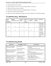
.... Electrical malfunction. Replace if necessary. Electrical malfunction. 26 SOLUTIONS Have batteries checked for service. Replace if necessary. Contact dealer/Invacare for shorted cell. Part No. 1118386 Replace if necessary. ❑ Ensure that casters are free of corrosion. Battery indicator ...damaged. SECTION 4-SAFETY INSPECTION/TROUBLESHOOTING ❑ Clean upholstery and armrests. ❑ Inspect charger AC power cord for damage. Have charger checked. Charger malfunction. Poor connections between charger and wheelchair. Contact dealer/Invacare.
.... Electrical malfunction. Replace if necessary. Electrical malfunction. 26 SOLUTIONS Have batteries checked for service. Replace if necessary. Contact dealer/Invacare for shorted cell. Part No. 1118386 Replace if necessary. ❑ Ensure that casters are free of corrosion. Battery indicator ...damaged. SECTION 4-SAFETY INSPECTION/TROUBLESHOOTING ❑ Clean upholstery and armrests. ❑ Inspect charger AC power cord for damage. Have charger checked. Charger malfunction. Poor connections between charger and wheelchair. Contact dealer/Invacare.
Owners Manual
Page 27
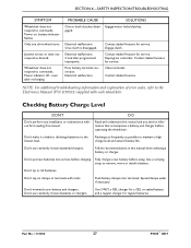
...controller. Use a carrying strap to the Electronics Manual (P/N 1110532) supplied with tools. Don't tip or tilt batteries. Power on clamps or terminals with each wheelchair. Power indicator off - Use ONLY a GEL charger for a GEL or sealed battery and a regular charger for service. ...One clutch is disengaged. Contact dealer/Invacare for regular batteries. DO Read and understand this manual and any installation ...
...controller. Use a carrying strap to the Electronics Manual (P/N 1110532) supplied with tools. Don't tip or tilt batteries. Power on clamps or terminals with each wheelchair. Power indicator off - Use ONLY a GEL charger for a GEL or sealed battery and a regular charger for service. ...One clutch is disengaged. Contact dealer/Invacare for regular batteries. DO Read and understand this manual and any installation ...

Owners Manual
Page 29
... notification of the joystick housing. C. GREEN LED is lit, indicating batteries are moderately charged. Recharge batteries before taking a long trip. Power is detected by the control module. Recharge batteries as soon as a system diagnostic device when a fault is on the status of charge...29 P9000™ XDT Only AMBER LEDs are lit, indicating batteries are running out of the wheelchair - 1. A specific number of flashes of the LEDs indicate the type of the wheelchair status. Fault indication (Flash Codes). Only RED LED is lit, indicating well charged batteries. ...
... notification of the joystick housing. C. GREEN LED is lit, indicating batteries are moderately charged. Recharge batteries before taking a long trip. Power is detected by the control module. Recharge batteries as soon as a system diagnostic device when a fault is on the status of charge...29 P9000™ XDT Only AMBER LEDs are lit, indicating batteries are running out of the wheelchair - 1. A specific number of flashes of the LEDs indicate the type of the wheelchair status. Fault indication (Flash Codes). Only RED LED is lit, indicating well charged batteries. ...

Owners Manual
Page 30
... to the electronics manual (Part Number 1110532). Refer to Neutral. P9000™ XDT 30 Part No. 1118386 DEFINITION Power is flash- ming, inhibit and/or charg- The batteries should be displayed at -Power-Up mode. The steady LEDs indicate nating with steady display. The current state of battery charge will be charged... are off. Joystick is low. Joystick has detected Out-of the ing mode. Joystick is flashing. Left RED LED is in Speed Limit ing. SECTION 5-WHEELCHAIR OPERATION DISPLAY DESCRIPTION All LEDs are on implies reduced battery charge...
... to the electronics manual (Part Number 1110532). Refer to Neutral. P9000™ XDT 30 Part No. 1118386 DEFINITION Power is flash- ming, inhibit and/or charg- The batteries should be displayed at -Power-Up mode. The steady LEDs indicate nating with steady display. The current state of battery charge will be charged... are off. Joystick is low. Joystick has detected Out-of the ing mode. Joystick is flashing. Left RED LED is in Speed Limit ing. SECTION 5-WHEELCHAIR OPERATION DISPLAY DESCRIPTION All LEDs are on implies reduced battery charge...

Owners Manual
Page 31
... that direction. This exercise will indicate one of the following : 1. B. NOTE: After turning power on page 31. The wheelchair has automatic speed and direction compensation to Turning the Power On/Off on , all indicators will light briefly and the display gauge will help you learn ...smooth control of speed and direction. It is equipped with 360 degrees of mobility for ease of the power chair. 2. Refer to minimize corrections. SECTION 5-WHEELCHAIR OPERATION Operating the Wheelchair NOTE: For this procedure, refer to FIGURE 5.2 on when the joystick is out of neutral. This...
... that direction. This exercise will indicate one of the following : 1. B. NOTE: After turning power on page 31. The wheelchair has automatic speed and direction compensation to Turning the Power On/Off on , all indicators will light briefly and the display gauge will help you learn ...smooth control of speed and direction. It is equipped with 360 degrees of mobility for ease of the power chair. 2. Refer to minimize corrections. SECTION 5-WHEELCHAIR OPERATION Operating the Wheelchair NOTE: For this procedure, refer to FIGURE 5.2 on when the joystick is out of neutral. This...
Owners Manual
Page 47
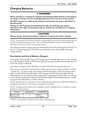
...a zero reading at the same time. Description and Use of electrical current drawn within a given time to charge a battery is anticipated the wheelchair will help you understand this automatic process are not supplied, consult a qualified service technician for a short period of time. NOTE: As a... the green light will stay illuminated for each charger (supplied or purchased). DO NOT attempt to recharge the batteries and operate the power wheelchair at a fully charged condition. Use the recharging plug located on the front of off when full charge is reduced, and the...
...a zero reading at the same time. Description and Use of electrical current drawn within a given time to charge a battery is anticipated the wheelchair will help you understand this automatic process are not supplied, consult a qualified service technician for a short period of time. NOTE: As a... the green light will stay illuminated for each charger (supplied or purchased). DO NOT attempt to recharge the batteries and operate the power wheelchair at a fully charged condition. Use the recharging plug located on the front of off when full charge is reduced, and the...
Owners Manual
Page 48
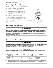
.... However, warnings are frequently noted on page 50. CHAIR SEAT WIDTH 18- Remove the battery boxes and tray from the wheelchair. NOTE: Invacare recommends that both batteries be replaced. inches 2 18-inches 2 QTY VOLTS 12 12 BATTERY SIZE U1 Group 22NF REMARKS Deep...VAC wall outlet. 3. Read them carefully, otherwise injury or damage can occur. Attach the battery charger connector to use as the power source for service. Charger Port FIGURE 11.2 Connecting the Battery Charger Replacing the Batteries ƽ WARNING Most batteries are based on ...
.... However, warnings are frequently noted on page 50. CHAIR SEAT WIDTH 18- Remove the battery boxes and tray from the wheelchair. NOTE: Invacare recommends that both batteries be replaced. inches 2 18-inches 2 QTY VOLTS 12 12 BATTERY SIZE U1 Group 22NF REMARKS Deep...VAC wall outlet. 3. Read them carefully, otherwise injury or damage can occur. Attach the battery charger connector to use as the power source for service. Charger Port FIGURE 11.2 Connecting the Battery Charger Replacing the Batteries ƽ WARNING Most batteries are based on ...
Owners Manual
Page 51
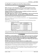
...the battery lifting strap, (+) side to POSITIVE (+) battery terminal/post and (-) side to NEGATIVE (-) battery terminal/post. Invacare strongly recommends that the battery acid will not spill. Refer to the battery manufacturer for the proper lifting strap and/or battery...battery box(es), reverse the following note. SECTION 11-BATTERIES Installing/Removing Batteries Into/From Battery Boxes ƽ WARNING Make sure power to the wheelchair is the most convenient method and assures that battery installation and battery replacement ALWAYS be done by a qualified technician. NOTE: For...
...the battery lifting strap, (+) side to POSITIVE (+) battery terminal/post and (-) side to NEGATIVE (-) battery terminal/post. Invacare strongly recommends that the battery acid will not spill. Refer to the battery manufacturer for the proper lifting strap and/or battery...battery box(es), reverse the following note. SECTION 11-BATTERIES Installing/Removing Batteries Into/From Battery Boxes ƽ WARNING Make sure power to the wheelchair is the most convenient method and assures that battery installation and battery replacement ALWAYS be done by a qualified technician. NOTE: For...

Owners Manual
Page 60
...WARNING If clutch handles are pointing towards the inside of the wheelchair. • To Disengage: turn the clutch handles until the power is tightened securely - NEVER try to turn the clutch handles towards the rear of wheelchair) Clutch Handle Clutch Handle FIGURE 12.1 Engaging/Disengaging the ...wrong direction as shown in these directions. To engage/disengage the clutches: 1. NOTE: For this procedure, refer to maneuver the wheelchair without power. SECTION 12-CLUTCH/MOTOR LOCK SECTION 12-CLUTCH/MOTOR LOCK ƽ WARNING After ANY adjustments, repair or service and BEFORE use,...
...WARNING If clutch handles are pointing towards the inside of the wheelchair. • To Disengage: turn the clutch handles until the power is tightened securely - NEVER try to turn the clutch handles towards the rear of wheelchair) Clutch Handle Clutch Handle FIGURE 12.1 Engaging/Disengaging the ...wrong direction as shown in these directions. To engage/disengage the clutches: 1. NOTE: For this procedure, refer to maneuver the wheelchair without power. SECTION 12-CLUTCH/MOTOR LOCK SECTION 12-CLUTCH/MOTOR LOCK ƽ WARNING After ANY adjustments, repair or service and BEFORE use,...
Owners Manual
Page 62
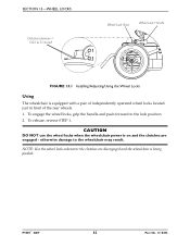
CAUTION DO NOT use the wheel locks when the wheelchair power is equipped with a pair of independently operated wheel locks located just in front of the rear wheels. 1. SECTION 13-WHEEL LOCKS Distance between = 5/32 to 5/...16-inch Wheel Lock Shoe Wheel Lock Handle FIGURE 13.1 Installing/Adjusting/Using the Wheel Locks Using The wheelchair is on and the clutches are disengaged and the wheelchair is being pushed. To engage the wheel locks, grip the handle and push forward to the...
CAUTION DO NOT use the wheel locks when the wheelchair power is equipped with a pair of independently operated wheel locks located just in front of the rear wheels. 1. SECTION 13-WHEEL LOCKS Distance between = 5/32 to 5/...16-inch Wheel Lock Shoe Wheel Lock Handle FIGURE 13.1 Installing/Adjusting/Using the Wheel Locks Using The wheelchair is on and the clutches are disengaged and the wheelchair is being pushed. To engage the wheel locks, grip the handle and push forward to the...
Owners Manual
Page 65
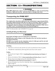
...advised when it is fully open and the seat rails are positioned in this procedure, refer to avoid injury. Make sure to move an unoccupied power wheelchair. DO NOT place hand or fingers on the seat rails until the seat rails are fully seated into the side frame H-blocks. Unfolding 1. ... to Removing/Installing the Battery Boxes on page 66. Use proper lifting techniques (lift with your legs) to FIGURE 15.1 on page 49. 2. Invacare recommends using two assistants and making thorough preparations. NOTE: For this manual. Part No. 1118386 65 P9000™ XDT Folding 1.
...advised when it is fully open and the seat rails are positioned in this procedure, refer to avoid injury. Make sure to move an unoccupied power wheelchair. DO NOT place hand or fingers on the seat rails until the seat rails are fully seated into the side frame H-blocks. Unfolding 1. ... to Removing/Installing the Battery Boxes on page 66. Use proper lifting techniques (lift with your legs) to FIGURE 15.1 on page 49. 2. Invacare recommends using two assistants and making thorough preparations. NOTE: For this manual. Part No. 1118386 65 P9000™ XDT Folding 1.


