Owners Manual
Page 3
...OF CONTENTS ...2 REFERENCE DOCUMENTS 2 REGISTER YOUR PRODUCT 6 SPECIAL NOTES 7 LABEL LOCATIONS 9 M91 Standard...9 M91 Heavy Duty...10 All Wheelchairs...10 TYPICAL PRODUCT PARAMETERS 11 PRONTO M91...11 SECTION 1-GENERAL GUIDELINES 13 Controller Settings/Repair or Service 13 Accessories Information ...13 Operation...OF WHEELCHAIRS 20 Stability and Balance...20 Coping With Everyday Obstacles...21 Pinch Points...22 A Note to Wheelchair Assistants ...22 Lifting/Stairways ...23 Transferring To and From Other Seats 24 Reaching, Leaning and Bending - Forward 25 Reaching and Bending - Backward...
...OF CONTENTS ...2 REFERENCE DOCUMENTS 2 REGISTER YOUR PRODUCT 6 SPECIAL NOTES 7 LABEL LOCATIONS 9 M91 Standard...9 M91 Heavy Duty...10 All Wheelchairs...10 TYPICAL PRODUCT PARAMETERS 11 PRONTO M91...11 SECTION 1-GENERAL GUIDELINES 13 Controller Settings/Repair or Service 13 Accessories Information ...13 Operation...OF WHEELCHAIRS 20 Stability and Balance...20 Coping With Everyday Obstacles...21 Pinch Points...22 A Note to Wheelchair Assistants ...22 Lifting/Stairways ...23 Transferring To and From Other Seats 24 Reaching, Leaning and Bending - Forward 25 Reaching and Bending - Backward...
Owners Manual
Page 14
...wheelchair. DO NOT operate on the frame of the wheelchair may result in the Off position. Invacare strongly recommends proceeding down ramps or traverse slopes greater than 9°. DO NOT store items ... ramps or slopes at half speed or slower and to stop a moving parts to lift the wheelchair by means of any removable (detachable) parts. Doing so may cause your wheelchair... NOT stand on an incline. NEVER leave an unoccupied wheelchair on the footplates/footboard. Pronto® M91™ with a water, ice or oil film. SECTION 1-GENERAL GUIDELINES DO NOT shift your weight...
...wheelchair. DO NOT operate on the frame of the wheelchair may result in the Off position. Invacare strongly recommends proceeding down ramps or traverse slopes greater than 9°. DO NOT store items ... ramps or slopes at half speed or slower and to stop a moving parts to lift the wheelchair by means of any removable (detachable) parts. Doing so may cause your wheelchair... NOT stand on an incline. NEVER leave an unoccupied wheelchair on the footplates/footboard. Pronto® M91™ with a water, ice or oil film. SECTION 1-GENERAL GUIDELINES DO NOT shift your weight...
Owners Manual
Page 22
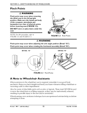
...; WARNING Pinch point may occur when rotating the footboard assembly (Detail "B"). These must NEVER be used to move the wheelchair or as lifting supports, as arms or legrests. Pronto® M91™ with SureStep® 22 Part No 1141450 SECTION 3-SAFETY/HANDLING OF WHEELCHAIRS Pinch Points ƽ WARNING Pinch point may be...
...; WARNING Pinch point may occur when rotating the footboard assembly (Detail "B"). These must NEVER be used to move the wheelchair or as lifting supports, as arms or legrests. Pronto® M91™ with SureStep® 22 Part No 1141450 SECTION 3-SAFETY/HANDLING OF WHEELCHAIRS Pinch Points ƽ WARNING Pinch point may be...
Owners Manual
Page 23
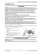
... to avoid injury. Rear Frame Front Forks (Front Edge) 2. Use proper lifting techniques (lift with your back straight. 3. If moving the wheelchair between 203 and 318 lbs. Part No 1141450 23 Pronto® M91™ with batteries and without the user is between floors when an elevator is...to move an occupied power wheelchair between floors by means of the front forks as hand hold supports. Invacare recommends using a stairway. It is necessary: 1. Use an elevator to lift the wheelchair by the rear frame and the front forks - DO NOT attempt to move an unoccupied...
... to avoid injury. Rear Frame Front Forks (Front Edge) 2. Use proper lifting techniques (lift with your back straight. 3. If moving the wheelchair between 203 and 318 lbs. Part No 1141450 23 Pronto® M91™ with batteries and without the user is between floors when an elevator is...to move an occupied power wheelchair between floors by means of the front forks as hand hold supports. Invacare recommends using a stairway. It is necessary: 1. Use an elevator to lift the wheelchair by the rear frame and the front forks - DO NOT attempt to move an unoccupied...
Owners Manual
Page 26
... operate and lock securely. ❑ Ensure armrest pads sit flush against arm tubes. ❑ Ensure seat is secured to one side). ❑ Ensure arms are lifted and spun when disengaged (freewheeling). ❑ Ensure wheel/fork assembly has proper tension when caster is functional. SECTION 4-SAFETY INSPECTION/TROUBLESHOOTING SECTION 4-SAFETY INSPECTION/ TROUBLESHOOTING... drag or pull to wheelchair frame. ❑ Ensure seat release latch is spun. Replace if necessary. ❑ Ensure casters are present and legible. Pronto® M91™ with any other vehicle.
... operate and lock securely. ❑ Ensure armrest pads sit flush against arm tubes. ❑ Ensure seat is secured to one side). ❑ Ensure arms are lifted and spun when disengaged (freewheeling). ❑ Ensure wheel/fork assembly has proper tension when caster is functional. SECTION 4-SAFETY INSPECTION/TROUBLESHOOTING SECTION 4-SAFETY INSPECTION/ TROUBLESHOOTING... drag or pull to wheelchair frame. ❑ Ensure seat release latch is spun. Replace if necessary. ❑ Ensure casters are present and legible. Pronto® M91™ with any other vehicle.

Owners Manual
Page 27
... ❑ Loosen/tighten caster locknut if wheel wobbles noticeably or binds to a stop. ❑ Ensure all caster/wheel/fork/headtube fasteners are lifted and spun when disengaged (free‐wheeling). ❑ Ensure wheel/fork assembly has proper tension when caster is spun. Replace if worn or ...components for flat spots and wear. ❑ Ensure arm pivot points are not worn and/or loose. Part No 1141450 27 Pronto® M91™ with SureStep® Replace if necessary. ❑ Inspect tires for signs of debris. Replace if necessary. ❑ Verify that the...
... ❑ Loosen/tighten caster locknut if wheel wobbles noticeably or binds to a stop. ❑ Ensure all caster/wheel/fork/headtube fasteners are lifted and spun when disengaged (free‐wheeling). ❑ Ensure wheel/fork assembly has proper tension when caster is spun. Replace if worn or ...components for flat spots and wear. ❑ Ensure arm pivot points are not worn and/or loose. Part No 1141450 27 Pronto® M91™ with SureStep® Replace if necessary. ❑ Inspect tires for signs of debris. Replace if necessary. ❑ Verify that the...
Owners Manual
Page 35
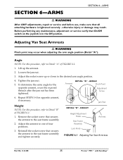
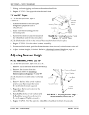
Lift up or down to Detail "B" of FIGURE 6.1. 1. Remove the socket screw that secures the armrest to one of FIGURE 6.1. 1. otherwise injury or damage may occur ... nut has been tightened. HEIGHT Height Adjustment Holes Seat Frame Assembly Lock Knob Armrest FIGURE 6.1 Adjusting Van Seat Armrests Part No 1141450 35 Pronto® M91™ with SureStep® Adjusting Van Seat Armrests ƽ WARNING Pinch point may result. Tighten the jam nut. 5. Armrest DETAIL "A" -
Lift up or down to Detail "B" of FIGURE 6.1. 1. Remove the socket screw that secures the armrest to one of FIGURE 6.1. 1. otherwise injury or damage may occur ... nut has been tightened. HEIGHT Height Adjustment Holes Seat Frame Assembly Lock Knob Armrest FIGURE 6.1 Adjusting Van Seat Armrests Part No 1141450 35 Pronto® M91™ with SureStep® Adjusting Van Seat Armrests ƽ WARNING Pinch point may result. Tighten the jam nut. 5. Armrest DETAIL "A" -
Owners Manual
Page 36
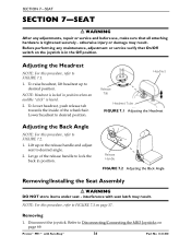
... up on page 69. Adjusting the Back Angle NOTE: For this procedure, refer to FIGURE 7.3 on page 37. Lift up to FIGURE 7.2. 1. NOTE: For this procedure, refer to desired position. NOTE: Headrest is locked in the Off position. Let go of the wheelchair. Adjusting ... joystick is in position when an audible "click" is heard. 2. Lower headrest to FIGURE 7.1. 1. interference with SureStep® 36 Part No 1141450 Removing 1. Pronto® M91™ with seat latch may result.
... up on page 69. Adjusting the Back Angle NOTE: For this procedure, refer to FIGURE 7.3 on page 37. Lift up to FIGURE 7.2. 1. NOTE: For this procedure, refer to desired position. NOTE: Headrest is locked in the Off position. Let go of the wheelchair. Adjusting ... joystick is in position when an audible "click" is heard. 2. Lower headrest to FIGURE 7.1. 1. interference with SureStep® 36 Part No 1141450 Removing 1. Pronto® M91™ with seat latch may result.
Owners Manual
Page 46
...Tube Footplate Footrest Release Lever 2. Reposition the lower footrest to wheelchair). Coved Washer Lower Footrest 5. Locknut Hex Bolt 3. Pronto® M91™ with SureStep® 46 Part No 1141450 FIGURE 9.2 Installing/Removing Front Riggings - 70° and 70° Taper ...for opposite side of the wheelchair until it locks into mounting tube. 3. Repeat STEPS 1‐5 for the other footrest assembly. 5. Lift up on front rigging and remove from the footrest(s). 2. To remove the footrest, push the footrest release lever inward, rotate footrest ...
...Tube Footplate Footrest Release Lever 2. Reposition the lower footrest to wheelchair). Coved Washer Lower Footrest 5. Locknut Hex Bolt 3. Pronto® M91™ with SureStep® 46 Part No 1141450 FIGURE 9.2 Installing/Removing Front Riggings - 70° and 70° Taper ...for opposite side of the wheelchair until it locks into mounting tube. 3. Repeat STEPS 1‐5 for the other footrest assembly. 5. Lift up on front rigging and remove from the footrest(s). 2. To remove the footrest, push the footrest release lever inward, rotate footrest ...
Owners Manual
Page 53
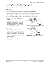
... wheelchair until desired height is perpendicular to correct height by loosening nut and sliding the lower footrest assembly up on the wheelchair frame. 3. Lift up or down until it locks in place. 4. Installing 1. Repeat STEPS 1‐ 2 for the opposite legrest. 5. NOTE: The... release handle toward the inside of wheelchair. Bolt/Nut FIGURE 9.13 Installing/Removing Elevating Legrests Part No 1141450 53 Pronto® M91™ with SureStep® SECTION 9-FRONT RIGGINGS Installing/Removing Elevating Legrests NOTE: For this procedure, refer to the outside of ...
... wheelchair until desired height is perpendicular to correct height by loosening nut and sliding the lower footrest assembly up on the wheelchair frame. 3. Lift up or down until it locks in place. 4. Installing 1. Repeat STEPS 1‐ 2 for the opposite legrest. 5. NOTE: The... release handle toward the inside of wheelchair. Bolt/Nut FIGURE 9.13 Installing/Removing Elevating Legrests Part No 1141450 53 Pronto® M91™ with SureStep® SECTION 9-FRONT RIGGINGS Installing/Removing Elevating Legrests NOTE: For this procedure, refer to the outside of ...

Owners Manual
Page 55
... the top shroud to the base frame (Detail "A"). • Front Shroud ‐ Turn release knob ¼‐turn to the unlocked position and lift up to replace flat free tires. Before performing any adjustments, repair or service and before use, make sure that all attaching hardware is in the...the Wheel Rim ƽ WARNING DO NOT attempt to remove front shroud from base frame hooks (Detail "B"). Part No 1141450 55 Pronto® M91™ with continued use of the wheelchair. otherwise injury or damage may experience flat spots on the wheels. Flat spots will vanish with SureStep®...
... the top shroud to the base frame (Detail "A"). • Front Shroud ‐ Turn release knob ¼‐turn to the unlocked position and lift up to replace flat free tires. Before performing any adjustments, repair or service and before use, make sure that all attaching hardware is in the...the Wheel Rim ƽ WARNING DO NOT attempt to remove front shroud from base frame hooks (Detail "B"). Part No 1141450 55 Pronto® M91™ with continued use of the wheelchair. otherwise injury or damage may experience flat spots on the wheels. Flat spots will vanish with SureStep®...
Owners Manual
Page 59
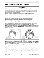
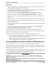
...battery cable(s) to neutralize the battery acid. Part No 1141450 59 Pronto® M91™ with mounting holes through the terminal. An electrical short may occur and serious...have the reversed terminal configuration MUST NOT be used - Avoid storage or use a battery lifting strap when lifting a battery. otherwise serious injury or damage may occur. Mounting Holes POSITIVE (+) Battery ...to these areas to contact both battery terminal(s)/post(s) at the same time. Invacare strongly recommends that battery installation and battery replacement always be connected to the battery ...
...battery cable(s) to neutralize the battery acid. Part No 1141450 59 Pronto® M91™ with mounting holes through the terminal. An electrical short may occur and serious...have the reversed terminal configuration MUST NOT be used - Avoid storage or use a battery lifting strap when lifting a battery. otherwise serious injury or damage may occur. Mounting Holes POSITIVE (+) Battery ...to these areas to contact both battery terminal(s)/post(s) at the same time. Invacare strongly recommends that battery installation and battery replacement always be connected to the battery ...
Owners Manual
Page 60
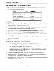
... necessary, connect the wiring harness to position the battery into the battery tray: • Batteries With Built In Lifting Strap ‐ Use built in STEP 5. Pronto® M91™ with the rear battery. Refer to Connecting/ Disconnecting the Battery Wiring Harness on page 69. 3. Perform ...Seat Assembly on page 55. 5. SECTION 11-BATTERIES Installing/Removing the Batteries NOTE: For this section on one of the following tools available: TOOL Battery Lifting Strap 1/2-inch (6 pt) Box Wrench 7/16-inch (6pt) Box Wrench 3/8-inch (6pt) Box Wrench Diagonal Cutters QTY 1 1 1 1 1 ...
... necessary, connect the wiring harness to position the battery into the battery tray: • Batteries With Built In Lifting Strap ‐ Use built in STEP 5. Pronto® M91™ with the rear battery. Refer to Connecting/ Disconnecting the Battery Wiring Harness on page 69. 3. Perform ...Seat Assembly on page 55. 5. SECTION 11-BATTERIES Installing/Removing the Batteries NOTE: For this section on one of the following tools available: TOOL Battery Lifting Strap 1/2-inch (6 pt) Box Wrench 7/16-inch (6pt) Box Wrench 3/8-inch (6pt) Box Wrench Diagonal Cutters QTY 1 1 1 1 1 ...
Owners Manual
Page 61
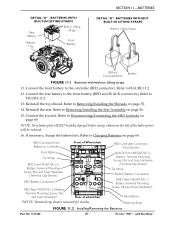
... Strap FIGURE 11.2 Installing/Removing the Batteries Part No 1141450 61 Pronto® M91™ with /without Lifting straps 11. DETAIL "A" - BATTERIES WITH BUILT-IN LIFTING STRAPS Rear Battery Battery Tray Built-in Lifting Straps Front Battery SECTION 11-BATTERIES DETAIL "B" - Refer to Charging Batteries on... page 36. 15. BATTERIES WITHOUT BUILT-IN LIFTING STRAPS Battery Lifting Straps Battery Terminals/Posts Battery FIGURE 11.1 Batteries with SureStep® Connect the rear battery to FIGURE 11.2....
... Strap FIGURE 11.2 Installing/Removing the Batteries Part No 1141450 61 Pronto® M91™ with /without Lifting straps 11. DETAIL "A" - BATTERIES WITH BUILT-IN LIFTING STRAPS Rear Battery Battery Tray Built-in Lifting Straps Front Battery SECTION 11-BATTERIES DETAIL "B" - Refer to Charging Batteries on... page 36. 15. BATTERIES WITHOUT BUILT-IN LIFTING STRAPS Battery Lifting Straps Battery Terminals/Posts Battery FIGURE 11.1 Batteries with SureStep® Connect the rear battery to FIGURE 11.2....
Owners Manual
Page 62
...FIGURE 11.1). • Batteries Without Built‐in the Off position and disconnect joystick. Refer to the front battery wiring harness. Pronto® M91™ with the front battery. Refer to carpeting or floor covering. 2. All battery terminal covers (two on the front battery and two on..., threaded portion of the battery tray. 6. Repeat STEP 10 to use. Verify the joystick On/Off switch is in Lifting Strap‐ Use the battery lifting strap to Disconnecting/Connecting the MK5 Joysticks on one to the controller cable (RED), and the rear battery has two connectors...
...FIGURE 11.1). • Batteries Without Built‐in the Off position and disconnect joystick. Refer to the front battery wiring harness. Pronto® M91™ with the front battery. Refer to carpeting or floor covering. 2. All battery terminal covers (two on the front battery and two on..., threaded portion of the battery tray. 6. Repeat STEP 10 to use. Verify the joystick On/Off switch is in Lifting Strap‐ Use the battery lifting strap to Disconnecting/Connecting the MK5 Joysticks on one to the controller cable (RED), and the rear battery has two connectors...
