
User Guide
Page 3
...the following Intel® Server Boards and Platforms: Intel® Server Board SE7520JR2 Intel® Server Board SE7320VP2 Intel® Server Platform SR2400SYS (integrated system) Intel® Server Platform SR2400SYSD2 (integrated system) 1 For complete technical specifications and additional technical information, see the Intel® Server Chassis ...front panel board, fans, power supply and other components you may need, troubleshooting information, and instructions on how to add and replace components on adding and replacing components. Intel® Server Chassis SR2400/SR2400DC User ...
...the following Intel® Server Boards and Platforms: Intel® Server Board SE7520JR2 Intel® Server Board SE7320VP2 Intel® Server Platform SR2400SYS (integrated system) Intel® Server Platform SR2400SYSD2 (integrated system) 1 For complete technical specifications and additional technical information, see the Intel® Server Chassis ...front panel board, fans, power supply and other components you may need, troubleshooting information, and instructions on how to add and replace components on adding and replacing components. Intel® Server Chassis SR2400/SR2400DC User ...

User Guide
Page 4
... the Intel Server Platform SR2400JR2. 3 Before purchasing any required options, refer to your server board documentation to below as the "hardware box" One 700-W power supply (AC version) or one 600-W power supply (DC version), installed in the chassis Low-profile PCI-X riser, installed in the chassis CD-ROM / DVD drive tray, installed in the chassis Four system...
... the Intel Server Platform SR2400JR2. 3 Before purchasing any required options, refer to your server board documentation to below as the "hardware box" One 700-W power supply (AC version) or one 600-W power supply (DC version), installed in the chassis Low-profile PCI-X riser, installed in the chassis CD-ROM / DVD drive tray, installed in the chassis Four system...
User Guide
Page 5
... cabinet and rails / brackets to mount the server into a rack Cable management arm Front bezel for the selected control panel option Processor(s) and heat sink(s) Memory DIMMs Intel® Management Module (Advanced or Professional) Tape drive kit Redundant fan kit (includes four fans) Redundant power supply Sixth drive SCSI or SATA kit Slimline CD...
... cabinet and rails / brackets to mount the server into a rack Cable management arm Front bezel for the selected control panel option Processor(s) and heat sink(s) Memory DIMMs Intel® Management Module (Advanced or Professional) Tape drive kit Redundant fan kit (includes four fans) Redundant power supply Sixth drive SCSI or SATA kit Slimline CD...

User Guide
Page 7
... circuit breaker of a centralized DC power system may be used on this server board. The safety ground conductor provides proper grounding only for the rack and other than 10 amps. Intel® Server Chassis SR2400/SR2400DC User Guide vii EMC Testing Before computer integration, make sure that the chassis, power supply, and other regulatory approvals of the...
... circuit breaker of a centralized DC power system may be used on this server board. The safety ground conductor provides proper grounding only for the rack and other than 10 amps. Intel® Server Chassis SR2400/SR2400DC User Guide vii EMC Testing Before computer integration, make sure that the chassis, power supply, and other regulatory approvals of the...

User Guide
Page 9
... disconnect device to the main (AC) power. Unplug all AC power cords from the system or from the covers. 3. Intel® Server Chassis SR2400/SR2400DC User Guide ix The power supply in this product. There may be easily accessible. The power button on the back of the system, follow these steps: 1. Turn off system AC power. After you have a separate AC...
... disconnect device to the main (AC) power. Unplug all AC power cords from the system or from the covers. 3. Intel® Server Chassis SR2400/SR2400DC User Guide ix The power supply in this product. There may be easily accessible. The power button on the back of the system, follow these steps: 1. Turn off system AC power. After you have a separate AC...

User Guide
Page 10
... you have not left loose tools or parts inside the system. 5. Connect all external cables and the AC power cord(s) to manufacturer's instructions. Dispose of airborne particles (other components are susceptible to access the power supply cord(s), because they serve as the product's main power disconnect. Away from sources of explosion if the battery is...
... you have not left loose tools or parts inside the system. 5. Connect all external cables and the AC power cord(s) to manufacturer's instructions. Dispose of airborne particles (other components are susceptible to access the power supply cord(s), because they serve as the product's main power disconnect. Away from sources of explosion if the battery is...
User Guide
Page 20
... Replacing a System Fan ...71 Replacing the Power Supply Distribution Module (AC Version 72 Replacing the Power Supply Distribution Module (DC Version 77 Installing or Replacing a Hot-swap Power Supply (AC Version 83 Removing a Hot-swap Power Supply 83 Installing a Hot-swap Power Supply 84 Installing or Replacing a Hot-swap Power Supply (DC Version 84 Removing a Hot-swap Power Supply 84 Installing a Hot-swap Power Supply 85 Installing...
... Replacing a System Fan ...71 Replacing the Power Supply Distribution Module (AC Version 72 Replacing the Power Supply Distribution Module (DC Version 77 Installing or Replacing a Hot-swap Power Supply (AC Version 83 Removing a Hot-swap Power Supply 83 Installing a Hot-swap Power Supply 84 Installing or Replacing a Hot-swap Power Supply (DC Version 84 Removing a Hot-swap Power Supply 84 Installing a Hot-swap Power Supply 85 Installing...
User Guide
Page 23
...Power Supply 85 Figure 77. Removing the Tape Drive Bay Filler Panel 90 Figure 81. Connecting the Tape Drive Cables 92 Figure 84. Disconnecting the Power Cable from the Server Board 78 Figure 70. Removing the Power Distribution Module 81 Figure 74. Disconnecting the Power Cables from the Server...the Flex and Power Cables 80 Figure 73. Inserting the Tape Drive Carrier into the Carrier 91 Figure 82. Removing a SATA or SCSI Backplane 87 Figure 78. Server Chassis Features 2 Product Certification Markings 102 Product Certification Markings 103 Intel® Server Chassis SR2400/...
...Power Supply 85 Figure 77. Removing the Tape Drive Bay Filler Panel 90 Figure 81. Connecting the Tape Drive Cables 92 Figure 84. Disconnecting the Power Cable from the Server Board 78 Figure 70. Removing the Power Distribution Module 81 Figure 74. Disconnecting the Power Cables from the Server...the Flex and Power Cables 80 Figure 73. Inserting the Tape Drive Carrier into the Carrier 91 Figure 82. Removing a SATA or SCSI Backplane 87 Figure 78. Server Chassis Features 2 Product Certification Markings 102 Product Certification Markings 103 Intel® Server Chassis SR2400/...
User Guide
Page 26
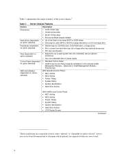
... Activity Power / Sleep System Status System Identification Hard Drive Activity With Intel® Local Control Panel: NIC1 Activity NIC2 Activity Power / Sleep System Status System Identification Hard Drive Activity LCD Display Screen Continued 6 Before purchasing any component noted as optional accessory) Two non-redundant fans in power supply Control Panel (dependent on option selected," refer to your server board. 2 Server Chassis...
... Activity Power / Sleep System Status System Identification Hard Drive Activity With Intel® Local Control Panel: NIC1 Activity NIC2 Activity Power / Sleep System Status System Identification Hard Drive Activity LCD Display Screen Continued 6 Before purchasing any component noted as optional accessory) Two non-redundant fans in power supply Control Panel (dependent on option selected," refer to your server board. 2 Server Chassis...
User Guide
Page 27
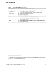
... use of video out of the front and back of the chassis. Server Chassis Features (continued) Power Supply (AC) One hot-swap 700-W power supply module 1+1 hot-swap redundant 700-W power supply (optional accessory) Power Supply (DC) One hot-swap 600-W power supply module 1+1 hot-swap redundant 600-W power supply (optional accessory) System Security Lockable front bezel (optional accessory) Chassis intrusion switch Lock attach...
... use of video out of the front and back of the chassis. Server Chassis Features (continued) Power Supply (AC) One hot-swap 700-W power supply module 1+1 hot-swap redundant 700-W power supply (optional accessory) Power Supply (DC) One hot-swap 600-W power supply module 1+1 hot-swap redundant 600-W power supply (optional accessory) System Security Lockable front bezel (optional accessory) Chassis intrusion switch Lock attach...

User Guide
Page 28
Power supply module housing F. SATA or SCSI backplane (optional component) C. air baffle for DC model differs) Figure 2. Component Identification Internal Components C A B E G D F H I . Control panel board E. Air baffle (AC model; Internal Component Locations 4 Fan module (shown with optional redundant fans) B. Processor air duct. (Memory DIMMs and processor(s) underneath) I TP01087 A. Drive bay area (drives not included) D. PCI Riser assembly H. Power distribution module G.
Power supply module housing F. SATA or SCSI backplane (optional component) C. air baffle for DC model differs) Figure 2. Component Identification Internal Components C A B E G D F H I . Control panel board E. Air baffle (AC model; Internal Component Locations 4 Fan module (shown with optional redundant fans) B. Processor air duct. (Memory DIMMs and processor(s) underneath) I TP01087 A. Drive bay area (drives not included) D. PCI Riser assembly H. Power distribution module G.
User Guide
Page 29
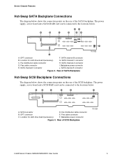
...Location for sixth drive board (accessory) F. SATA channel D connector J. The power supply, server board and a SCSI RAID card can be connected to the locations below. Flex cable connector C. Backplane power connector E. Server Chassis Features Hot-Swap SATA Backplane Connections The diagram below shows the connection .... Location for sixth drive board (accessory) G. The power supply, server board and a SATA RAID card can be connected to the locations below. Rear of SCSI Backplane TP01364 Intel® Server Chassis SR2400/SR2400DC User Guide 5 Backplane...
...Location for sixth drive board (accessory) F. SATA channel D connector J. The power supply, server board and a SCSI RAID card can be connected to the locations below. Flex cable connector C. Backplane power connector E. Server Chassis Features Hot-Swap SATA Backplane Connections The diagram below shows the connection .... Location for sixth drive board (accessory) G. The power supply, server board and a SATA RAID card can be connected to the locations below. Rear of SCSI Backplane TP01364 Intel® Server Chassis SR2400/SR2400DC User Guide 5 Backplane...
User Guide
Page 32
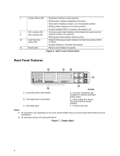
... receptacle for port identification. (2) AC back panel shown; See your server board documentation for optional redundant power supply) E. Figure 7. Blinking amber indicates a non-critical condition. Power supply fans (shown with optional power module installed) F. Blinking green indicates degraded performance. N Reset button Reboots and initializes the system. Low-profile add-in card bracket C. Full-height add-in card...
... receptacle for port identification. (2) AC back panel shown; See your server board documentation for optional redundant power supply) E. Figure 7. Blinking amber indicates a non-critical condition. Power supply fans (shown with optional power module installed) F. Blinking green indicates degraded performance. N Reset button Reboots and initializes the system. Low-profile add-in card bracket C. Full-height add-in card...

User Guide
Page 38
... DC external source. Removing and Installing the Chassis Cover Removing the Chassis Cover The Intel® Server Chassis SR2400/SR2400DC must be needed to add or replace components inside the chassis are hot-swappable. Except for the redundant power supply, none of the components inside of this book. Remove the shipping screw (if installed...
... DC external source. Removing and Installing the Chassis Cover Removing the Chassis Cover The Intel® Server Chassis SR2400/SR2400DC must be needed to add or replace components inside the chassis are hot-swappable. Except for the redundant power supply, none of the components inside of this book. Remove the shipping screw (if installed...

User Guide
Page 43
Power down the server and unplug all peripheral devices and connect the AC power cable or DC external source to pinch or disengage cables that may be flush with the top surface of the power supply. See the figure below. The front edge of the air duct should... Place the processor air duct over the processor socket(s). Remove the chassis cover. Plug in all peripheral devices and the AC power cable or DC external power. 3. Intel® Server Chassis SR2400/SR2400DC User Guide 19 For instructions, see "Installing the Chassis Cover." 8. For instructions, see "Installing the Processor...
Power down the server and unplug all peripheral devices and connect the AC power cable or DC external source to pinch or disengage cables that may be flush with the top surface of the power supply. See the figure below. The front edge of the air duct should... Place the processor air duct over the processor socket(s). Remove the chassis cover. Plug in all peripheral devices and the AC power cable or DC external power. 3. Intel® Server Chassis SR2400/SR2400DC User Guide 19 For instructions, see "Installing the Chassis Cover." 8. For instructions, see "Installing the Processor...

User Guide
Page 45
.... A large air baffle is installed between the power supply and the drive cage area. Use these steps only when it pushes away from the server, install the processor air dam as necessary for ... your system uses fixed drives, you have one air baffle that you remove the air baffle(s). For instructions, see "Installing the Chassis Cover." 10. Install the chassis cover. Depending on a server board... AC or a DC model of the backplane. Intel® Server Chassis SR2400/SR2400DC User Guide 21 Turn the processor air duct over to the server. Install the opposite end of the air dam...
.... A large air baffle is installed between the power supply and the drive cage area. Use these steps only when it pushes away from the server, install the processor air dam as necessary for ... your system uses fixed drives, you have one air baffle that you remove the air baffle(s). For instructions, see "Installing the Chassis Cover." 10. Install the chassis cover. Depending on a server board... AC or a DC model of the backplane. Intel® Server Chassis SR2400/SR2400DC User Guide 21 Turn the processor air duct over to the server. Install the opposite end of the air dam...

User Guide
Page 47
... baffle. 7. Remove the chassis cover. See letter "A" in the baffle. Installing the Large Hot-swap Air Baffle Intel® Server Chassis SR2400/SR2400DC User Guide 23 Lower the baffle into the chassis between the power supply and the back of this book. See "Safety Information." 2. Observe the safety and ESD precautions at the beginning...
... baffle. 7. Remove the chassis cover. See letter "A" in the baffle. Installing the Large Hot-swap Air Baffle Intel® Server Chassis SR2400/SR2400DC User Guide 23 Lower the baffle into the chassis between the power supply and the back of this book. See "Safety Information." 2. Observe the safety and ESD precautions at the beginning...

User Guide
Page 62
Insert the drive into the bay until it is not already installed, connect the SATA power cable adapter to you with the fixed drive kit. See letters "A" and "B" in the figure below. Install drives first into place. B A TP01161 Figure 34. If it clicks into the lower three drive bays for the easiest cable routing. 10. The power cable adapter was provided to the 3x2 power supply cable that extends from your power supply. 9. Installing the Fixed SATA Drive Power Cables 38
Insert the drive into the bay until it is not already installed, connect the SATA power cable adapter to you with the fixed drive kit. See letters "A" and "B" in the figure below. Install drives first into place. B A TP01161 Figure 34. If it clicks into the lower three drive bays for the easiest cable routing. 10. The power cable adapter was provided to the 3x2 power supply cable that extends from your power supply. 9. Installing the Fixed SATA Drive Power Cables 38
User Guide
Page 95
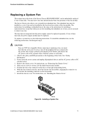
... and Upgrades Replacing a System Fan The system fans at the front of the Server Chassis SR2400/SR2400DC can be individually replaced if one of these fans fails, the power supply module must be replaced. The Server Chassis also allows you must first take the server out of four and are...the redundant set of service, turn off all peripheral devices and the AC power cable or DC external source. 3. Position the fan so the connector on the fan module. 7. Installing a System Fan Intel® Server Chassis SR2400/SR2400DC User Guide 71 You must be installed as the instructions...
... and Upgrades Replacing a System Fan The system fans at the front of the Server Chassis SR2400/SR2400DC can be individually replaced if one of these fans fails, the power supply module must be replaced. The Server Chassis also allows you must first take the server out of four and are...the redundant set of service, turn off all peripheral devices and the AC power cable or DC external source. 3. Position the fan so the connector on the fan module. 7. Installing a System Fan Intel® Server Chassis SR2400/SR2400DC User Guide 71 You must be installed as the instructions...

User Guide
Page 96
... SR2400DC, see "Removing the Fixed Drive Air Baffle (No Backplane Installed)" for instructions. To replace the power supply distribution module, use the following instructions. 1. The power supply distribution module is at the beginning of the Intel® Server Chassis SR2400. Remove the chassis cover. For instructions, see "Removing the PCI Riser Assembly." 72 If you are...
... SR2400DC, see "Removing the Fixed Drive Air Baffle (No Backplane Installed)" for instructions. To replace the power supply distribution module, use the following instructions. 1. The power supply distribution module is at the beginning of the Intel® Server Chassis SR2400. Remove the chassis cover. For instructions, see "Removing the PCI Riser Assembly." 72 If you are...
