User Guide
Page 5
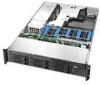
...one or more of the following items for your server: 5 Server rack cabinet and rails / brackets to mount the server into a rack Cable management arm Front bezel for the selected control panel option Processor(s) and heat sink(s) Memory DIMMs Intel® Management Module (Advanced or Professional) Tape... tested and can be used with your chassis, and for ordering information for Intel products, see http://www.support.intel.com/support/motherboards/server/chassis/SR2400/ 5 Before purchasing any optional items, refer to your server board documentation to determine which items are supported on your...
...one or more of the following items for your server: 5 Server rack cabinet and rails / brackets to mount the server into a rack Cable management arm Front bezel for the selected control panel option Processor(s) and heat sink(s) Memory DIMMs Intel® Management Module (Advanced or Professional) Tape... tested and can be used with your chassis, and for ordering information for Intel products, see http://www.support.intel.com/support/motherboards/server/chassis/SR2400/ 5 Before purchasing any optional items, refer to your server board documentation to determine which items are supported on your...

User Guide
Page 28
SATA or SCSI backplane (optional component) C. Control panel board E. Internal Component Locations 4 Drive bay area (drives not included) D. Air baffle (AC model; air baffle for DC model differs) Figure 2. PCI Riser assembly H. Processor air duct. (Memory DIMMs and processor(s) underneath) I TP01087 A. Fan module (shown with optional redundant fans) B. Power distribution module G. Component Identification Internal Components C A B E G D F H I . Power supply module housing F.
SATA or SCSI backplane (optional component) C. Control panel board E. Internal Component Locations 4 Drive bay area (drives not included) D. Air baffle (AC model; air baffle for DC model differs) Figure 2. PCI Riser assembly H. Processor air duct. (Memory DIMMs and processor(s) underneath) I TP01087 A. Fan module (shown with optional redundant fans) B. Power distribution module G. Component Identification Internal Components C A B E G D F H I . Power supply module housing F.

User Guide
Page 37
...) Antistatic wrist strap and conductive foam pad (recommended) System References All references to the safety instructions at the beginning of the chassis as the processor and memory DIMMs, see the instructions provided with your server product, pay close attention to left, right, front,...based on the server board, such as it would be positioned for adding and replacing chassis components. Hardware Installations and Upgrades 2 Hardware Installations and Upgrades Before You Begin Before working with the server board. See "Safety Information." Intel® Server Chassis SR2400/...
...) Antistatic wrist strap and conductive foam pad (recommended) System References All references to the safety instructions at the beginning of the chassis as the processor and memory DIMMs, see the instructions provided with your server product, pay close attention to left, right, front,...based on the server board, such as it would be positioned for adding and replacing chassis components. Hardware Installations and Upgrades 2 Hardware Installations and Upgrades Before You Begin Before working with the server board. See "Safety Information." Intel® Server Chassis SR2400/...

User Guide
Page 121
Equipment Log and Worksheets Equipment Log and Worksheets Equipment Log Use the blank equipment log provided here to record information about your server. Item Chassis Manufacturer Name and Model Number Serial Number Date Installed Server Board Processor Speed and Cache Memory Video Display Keyboard Mouse Floppy Drive CD-ROM Drive Tape Drive Hard Disk Drive Hard Disk Drive Hard Disk Drive Hard Disk Drive Hard Disk Drive Hard Disk Drive continued 97 You will need some of this information when you run the SSU.
Equipment Log and Worksheets Equipment Log and Worksheets Equipment Log Use the blank equipment log provided here to record information about your server. Item Chassis Manufacturer Name and Model Number Serial Number Date Installed Server Board Processor Speed and Cache Memory Video Display Keyboard Mouse Floppy Drive CD-ROM Drive Tape Drive Hard Disk Drive Hard Disk Drive Hard Disk Drive Hard Disk Drive Hard Disk Drive Hard Disk Drive continued 97 You will need some of this information when you run the SSU.

User Guide
Page 123
Power Usage Worksheet 1 Current (maximum) at voltage level: Device Baseboard, Front Panel Board and Fans Processor(s) Memory 3.5-inch Diskette Drive CD-ROM Drive DVD Rom Drive 1st Hard Drive 2nd Hard Drive 3rd Hard Drive 4th Hard Drive 5th ...Hard Drive 6th Hard Drive Tape Drive Expansion Board 1 Expansion Board 2 Expansion Board 3 Expansion Board 4 Expansion Board 5 Intel® Management Module Standard or Local Control Panel +3.3 V +5 V -5 V +12 V -12 V Total Current 5 V Standby 99 Worksheet, Calculating DC Power Usage Table 4. Equipment Log ...
Power Usage Worksheet 1 Current (maximum) at voltage level: Device Baseboard, Front Panel Board and Fans Processor(s) Memory 3.5-inch Diskette Drive CD-ROM Drive DVD Rom Drive 1st Hard Drive 2nd Hard Drive 3rd Hard Drive 4th Hard Drive 5th ...Hard Drive 6th Hard Drive Tape Drive Expansion Board 1 Expansion Board 2 Expansion Board 3 Expansion Board 4 Expansion Board 5 Intel® Management Module Standard or Local Control Panel +3.3 V +5 V -5 V +12 V -12 V Total Current 5 V Standby 99 Worksheet, Calculating DC Power Usage Table 4. Equipment Log ...