

User Guide
Page 1
Intel® Entry Server Chassis SC5299-E UP/DP/WS/BRP User Guide A Guide for Technically Qualified Assemblers of Intel® Identified Subassemblies/Products Intel Order Number D37596-004
Intel® Entry Server Chassis SC5299-E UP/DP/WS/BRP User Guide A Guide for Technically Qualified Assemblers of Intel® Identified Subassemblies/Products Intel Order Number D37596-004

User Guide
Page 2
... brands may occur. Copyright © 2006-2010, Intel Corporation. All Rights Reserved ii Intel® Entry Server Chassis SC5299-E UP/DP/WS/BRP User Guide Intel Corporation can not be claimed as provided in Intel's Terms and Conditions of Sale for such products, Intel assumes no liability whatsoever, and Intel disclaims any express or implied warranty, relating to...
... brands may occur. Copyright © 2006-2010, Intel Corporation. All Rights Reserved ii Intel® Entry Server Chassis SC5299-E UP/DP/WS/BRP User Guide Intel Corporation can not be claimed as provided in Intel's Terms and Conditions of Sale for such products, Intel assumes no liability whatsoever, and Intel disclaims any express or implied warranty, relating to...

User Guide
Page 3
... toute instruction. Vea Intel Server Boards and Server Chassis Safety Information en el Intel® Server Deployment Toolkit CD y/o en http://support.intel.com/ support/motherboards/server/sb/cs-010770.htm Intel® Entry Server Chassis SC5299-E UP/DP/WS/BRP User Guide iii See also Intel Server Boards and Server Chassis Safety Information on the Intel® Server Deployment...
... toute instruction. Vea Intel Server Boards and Server Chassis Safety Information en el Intel® Server Deployment Toolkit CD y/o en http://support.intel.com/ support/motherboards/server/sb/cs-010770.htm Intel® Entry Server Chassis SC5299-E UP/DP/WS/BRP User Guide iii See also Intel Server Boards and Server Chassis Safety Information on the Intel® Server Deployment...

User Guide
Page 4
... the narrow sides of the product and will void the UL listing and other parts. Take care to the safety instructions. iv Intel® Entry Server Chassis SC5299-E UP/DP/WS/BRP User Guide System power on/off: The power button DOES NOT turn off the server and disconnect the power...at an ESD workstation. If your server when handling parts. If one is a small plastic encased conductor that you may be extremely sensitive to chassis ground any unpainted metal surface on your jumpers do not have a small tab on power, telephone, and communication cables. Hold boards only by ...
... the narrow sides of the product and will void the UL listing and other parts. Take care to the safety instructions. iv Intel® Entry Server Chassis SC5299-E UP/DP/WS/BRP User Guide System power on/off: The power button DOES NOT turn off the server and disconnect the power...at an ESD workstation. If your server when handling parts. If one is a small plastic encased conductor that you may be extremely sensitive to chassis ground any unpainted metal surface on your jumpers do not have a small tab on power, telephone, and communication cables. Hold boards only by ...
User Guide
Page 5
.../DP/WS/BRP User Guide v At the back of this Manual Thank you identify components and their locations. Chapter 2 provides instructions on the Intel® Entry Server Chassis SC5299-E. In this chapter for step-by-step instructions and diagrams for installing or replacing components such as the fans, power supply, drives, and other...
.../DP/WS/BRP User Guide v At the back of this Manual Thank you identify components and their locations. Chapter 2 provides instructions on the Intel® Entry Server Chassis SC5299-E. In this chapter for step-by-step instructions and diagrams for installing or replacing components such as the fans, power supply, drives, and other...
User Guide
Page 6
... depend on this Web page, type the document or software name in the search field at http://support.intel.com/support/motherboards/server/chassis/sc5299-e/ Unless otherwise indicated in the product box vi Intel® Entry Server Chassis SC5299-E UP/DP/WS/BRP User Guide For this information or software For in the hardware kit •...
... depend on this Web page, type the document or software name in the search field at http://support.intel.com/support/motherboards/server/chassis/sc5299-e/ Unless otherwise indicated in the product box vi Intel® Entry Server Chassis SC5299-E UP/DP/WS/BRP User Guide For this information or software For in the hardware kit •...
User Guide
Page 7
... Tool is available under "Other Resources" at the right side of the screen at http://support.intel.com/support/motherboards/server/chassis/ sc5299-e Accessories or other Intel Spares and Configuration Guide server products Hardware (peripheral boards, adapter cards) and operating systems that have... system falls within the allowed power budget For software to manage your Intel® server Power Budget Tool at http://support.intel.com/support/motherboards/server/chassis/ sc5299-e Intel® System Management Software Intel® Entry Server Chassis SC5299-E UP/DP/WS/BRP User Guide vii
... Tool is available under "Other Resources" at the right side of the screen at http://support.intel.com/support/motherboards/server/chassis/ sc5299-e Accessories or other Intel Spares and Configuration Guide server products Hardware (peripheral boards, adapter cards) and operating systems that have... system falls within the allowed power budget For software to manage your Intel® server Power Budget Tool at http://support.intel.com/support/motherboards/server/chassis/ sc5299-e Intel® System Management Software Intel® Entry Server Chassis SC5299-E UP/DP/WS/BRP User Guide vii
User Guide
Page 9
...seguridad importantes iii Warnings ...iv Preface ...v About this Manual ...v Manual Organization ...v Product Contents, Order Options, and Accessories v Additional Information and Software vi Server Chassis Features 1 Component Identification ...3 Front View Components 3 Internal Components ...5 Back Panel Components 7 Front Panel ...8 Peripheral Devices ...9 Hard Disk Drives ...9 Front Bezel ... Installing or Removing a Server Board 20 Installing and Removing a Fixed Hard Drive 26 Installing a Fixed Hard Drive 26 Intel® Entry Server Chassis SC5299-E UP/DP/WS/BRP User Guide ix
...seguridad importantes iii Warnings ...iv Preface ...v About this Manual ...v Manual Organization ...v Product Contents, Order Options, and Accessories v Additional Information and Software vi Server Chassis Features 1 Component Identification ...3 Front View Components 3 Internal Components ...5 Back Panel Components 7 Front Panel ...8 Peripheral Devices ...9 Hard Disk Drives ...9 Front Bezel ... Installing or Removing a Server Board 20 Installing and Removing a Fixed Hard Drive 26 Installing a Fixed Hard Drive 26 Intel® Entry Server Chassis SC5299-E UP/DP/WS/BRP User Guide ix
User Guide
Page 10
... 98 Site Selection ...98 Equipment Handling Practices 98 Power and Electrical Warnings 98 System Access Warnings 99 Rack Mount Warnings 100 x Intel® Entry Server Chassis SC5299-E UP/DP/WS/BRP User Guide Removing a Fixed Hard Drive 32 Installing or Removing a DVD-ROM or CD-ROM Drive... Power Supply (BRP configuration only 53 Replacing a Hot Swap Power Supply Cage (BRP configuration only 54 Installing Feet for a Pedestal-configured Chassis 59 Hot Swap Drive Cage Upgrade Install Instructions (optional 61 Before You Begin ...61 Kits Required ...61 Tools and Supplies Needed 61 System...
... 98 Site Selection ...98 Equipment Handling Practices 98 Power and Electrical Warnings 98 System Access Warnings 99 Rack Mount Warnings 100 x Intel® Entry Server Chassis SC5299-E UP/DP/WS/BRP User Guide Removing a Fixed Hard Drive 32 Installing or Removing a DVD-ROM or CD-ROM Drive... Power Supply (BRP configuration only 53 Replacing a Hot Swap Power Supply Cage (BRP configuration only 54 Installing Feet for a Pedestal-configured Chassis 59 Hot Swap Drive Cage Upgrade Install Instructions (optional 61 Before You Begin ...61 Kits Required ...61 Tools and Supplies Needed 61 System...

User Guide
Page 12
... Warranty Service 146 Telephone Support ...147 Returning a Defective Product 147 F. Limited Warranty for Intel® Chassis Subassembly Products 145 Extent of Limited Warranty 145 Warranty Limitations and Exclusions 146 Limitations of Life / Product Recycling 155 xii Intel® Entry Server Chassis SC5299-E UP/DP/WS/BRP User Guide Regulatory and Compliance Information 149 Product Regulatory...
... Warranty Service 146 Telephone Support ...147 Returning a Defective Product 147 F. Limited Warranty for Intel® Chassis Subassembly Products 145 Extent of Limited Warranty 145 Warranty Limitations and Exclusions 146 Limitations of Life / Product Recycling 155 xii Intel® Entry Server Chassis SC5299-E UP/DP/WS/BRP User Guide Regulatory and Compliance Information 149 Product Regulatory...

User Guide
Page 13
... Figure 25. Drive Bay Slot Order 30 Figure 32. Cabling a Fixed Hard Drive 31 Figure 33. Removing Drive Cage EMI Shield from Chassis 15 Figure 13. Internal Components (UP Configuration 6 Figure 6. Front Panel Components 8 Figure 8. Optional Peripheral Devices (DP/WS/BRP configuration ... Figure 28. Removing 5.25-in Drive EMI Shield (DP/WS/BRP configuration shown 35 Intel® Entry Server Chassis SC5299-E UP/DP/WS/BRP User Guide xiii List of Intel® Entry Server Chassis SC5299-E 1 Figure 2. Internal Components (DP/WS/BRP Configuration 5 Figure 5. Installing the Front...
... Figure 25. Drive Bay Slot Order 30 Figure 32. Cabling a Fixed Hard Drive 31 Figure 33. Removing Drive Cage EMI Shield from Chassis 15 Figure 13. Internal Components (UP Configuration 6 Figure 6. Front Panel Components 8 Figure 8. Optional Peripheral Devices (DP/WS/BRP configuration ... Figure 28. Removing 5.25-in Drive EMI Shield (DP/WS/BRP configuration shown 35 Intel® Entry Server Chassis SC5299-E UP/DP/WS/BRP User Guide xiii List of Intel® Entry Server Chassis SC5299-E 1 Figure 2. Internal Components (DP/WS/BRP Configuration 5 Figure 5. Installing the Front...

User Guide
Page 14
...56. Removing Stud Screws from Front Panel 44 Figure 53. Attaching Latch Plate to Power Supply Cage 56 Figure 73. Opening PCI Add-in Chassis 50 Figure 63. Re-installing Fan Duct / System Fan Assembly (DP/WS/BRP configuration) ........ 48 Figure 60. Inserting Fixed Power Supply in...47 Figure 57. Removing Fixed Drive Cage EMI Shield from Chassis (DP/WS/BRP configuration shown) ...62 Figure 78. Attaching Filler Panel to Hot Swap Drive Cage (SAS/SATA drive cage illustrated).. 66 xiv Intel® Entry Server Chassis SC5299-E UP/DP/WS/BRP User Guide Locking Fixed Power Supply...
...56. Removing Stud Screws from Front Panel 44 Figure 53. Attaching Latch Plate to Power Supply Cage 56 Figure 73. Opening PCI Add-in Chassis 50 Figure 63. Re-installing Fan Duct / System Fan Assembly (DP/WS/BRP configuration) ........ 48 Figure 60. Inserting Fixed Power Supply in...47 Figure 57. Removing Fixed Drive Cage EMI Shield from Chassis (DP/WS/BRP configuration shown) ...62 Figure 78. Attaching Filler Panel to Hot Swap Drive Cage (SAS/SATA drive cage illustrated).. 66 xiv Intel® Entry Server Chassis SC5299-E UP/DP/WS/BRP User Guide Locking Fixed Power Supply...

User Guide
Page 15
.... Affixing Label to Rack Uprights 90 Figure 116. Detaching Inner Rack Rail from Chassis (DP/WS/BRP configuration shown). 84 Figure 107. Inserting Hot Swap Drive Cage into Rack 91 Intel® Entry Server Chassis SC5299-E UP/DP/WS/BRP User Guide xv Installing Hard Drive into Drive Carrier 75...Inner Rack Rails to Fan Bracket 67 Figure 85. Installing Plastic Retention Device in Hot Swap Drive Cage 79 Figure 102. Attaching Fan to Chassis (DP/WS/BRP configuration shown) ......... 89 Figure 115. Making Six-drive SAS/SATA Hot-Swap Drive Cage Backplane without ex- Removing Drive ...
.... Affixing Label to Rack Uprights 90 Figure 116. Detaching Inner Rack Rail from Chassis (DP/WS/BRP configuration shown). 84 Figure 107. Inserting Hot Swap Drive Cage into Rack 91 Intel® Entry Server Chassis SC5299-E UP/DP/WS/BRP User Guide xv Installing Hard Drive into Drive Carrier 75...Inner Rack Rails to Fan Bracket 67 Figure 85. Installing Plastic Retention Device in Hot Swap Drive Cage 79 Figure 102. Attaching Fan to Chassis (DP/WS/BRP configuration shown) ......... 89 Figure 115. Making Six-drive SAS/SATA Hot-Swap Drive Cage Backplane without ex- Removing Drive ...

User Guide
Page 17
Breakdown of Tables Table 1. System Environmental Specifications 95 Table 9. Accessories and Order Codes 11 Table 4. 420-W Power Supply Output Capability 93 Table 5. 550-W Power Supply Output Capability 94 Table 6. 670-W Power Supply Output Capability 94 Table 7. 650-W Power Supply Output Capability 95 Table 8. Product Regulatory Compliance Markings 151 Intel® Entry Server Chassis SC5299-E UP/DP/WS/BRP User Guide xvii Server Chassis Features 2 Table 3. List of Intel® Entry Server Chassis SC5299-E Configurations 1 Table 2.
Breakdown of Tables Table 1. System Environmental Specifications 95 Table 9. Accessories and Order Codes 11 Table 4. 420-W Power Supply Output Capability 93 Table 5. 550-W Power Supply Output Capability 94 Table 6. 670-W Power Supply Output Capability 94 Table 7. 650-W Power Supply Output Capability 95 Table 8. Product Regulatory Compliance Markings 151 Intel® Entry Server Chassis SC5299-E UP/DP/WS/BRP User Guide xvii Server Chassis Features 2 Table 3. List of Intel® Entry Server Chassis SC5299-E Configurations 1 Table 2.
User Guide
Page 19
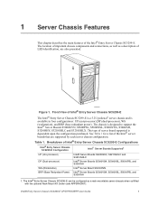
... that are also presented. See Table 1 for a list of LED identification, are supported by each server chassis configuration. The location of the Intel® Entry Server Chassis SC5299-E. Front View of Intel® Entry Server Chassis SC5299-E Configurations Intel® Entry Server Chassis SC5299-E Configuration Intel® Server Boards Supported1 UP (Uni-processor) DP (Dual-processor) WS (Workstation) BRP (Base Redundant...
... that are also presented. See Table 1 for a list of LED identification, are supported by each server chassis configuration. The location of the Intel® Entry Server Chassis SC5299-E. Front View of Intel® Entry Server Chassis SC5299-E Configurations Intel® Entry Server Chassis SC5299-E Configuration Intel® Server Boards Supported1 UP (Uni-processor) DP (Dual-processor) WS (Workstation) BRP (Base Redundant...

User Guide
Page 20
... a 550-W PFC tool-less fixed power supply • WS - ships with WS chassis configuration 2 Intel® Entry Server Chassis SC5299-E UP/DP/WS/BRP User Guide An additional module can be purchased as an accessory to http://support.intel.com/support/motherboards/server/ chassis/sc5299-e/. Peripherals Front panel Front Panel LEDs and displays NOTE: An optional SCSI...
... a 550-W PFC tool-less fixed power supply • WS - ships with WS chassis configuration 2 Intel® Entry Server Chassis SC5299-E UP/DP/WS/BRP User Guide An additional module can be purchased as an accessory to http://support.intel.com/support/motherboards/server/ chassis/sc5299-e/. Peripherals Front panel Front Panel LEDs and displays NOTE: An optional SCSI...

User Guide
Page 21
Front View Components (with Front Bezel Assembly) Intel® Entry Server Chassis SC5299-E UP/DP/WS/BRP User Guide 3 Server Chassis Features Feature Description USB • Two front panel USB ports NOTES: 1. Component Identification Front View Components A B C D E TP02345 A. 5.25-in Device Drive Bays B. Front Panel C. Drive Bay Access Door D. Front Panel USB Ports Figure 2. Power supply fan integrated into power supply module. Server Chassis Features Table 2. Door Lock E.
Front View Components (with Front Bezel Assembly) Intel® Entry Server Chassis SC5299-E UP/DP/WS/BRP User Guide 3 Server Chassis Features Feature Description USB • Two front panel USB ports NOTES: 1. Component Identification Front View Components A B C D E TP02345 A. 5.25-in Device Drive Bays B. Front Panel C. Drive Bay Access Door D. Front Panel USB Ports Figure 2. Power supply fan integrated into power supply module. Server Chassis Features Table 2. Door Lock E.

User Guide
Page 22
Server Chassis Features A B C D E TP00882 A. 5.25-in Device Drive Bays B. 3.5-in Device Drive Bay C. Front View Components (without Front Bezel Assembly) 4 Intel® Entry Server Chassis SC5299-E UP/DP/WS/BRP User Guide Hard Drive Cage D. Front Panel USB Ports Figure 3. Drive Bay EMI Shield (shown open) E.
Server Chassis Features A B C D E TP00882 A. 5.25-in Device Drive Bays B. 3.5-in Device Drive Bay C. Front View Components (without Front Bezel Assembly) 4 Intel® Entry Server Chassis SC5299-E UP/DP/WS/BRP User Guide Hard Drive Cage D. Front Panel USB Ports Figure 3. Drive Bay EMI Shield (shown open) E.

User Guide
Page 23
Tool-less Device Bay Locks B. 5.25-in Device Bays C. 3.5-in Card Guide G. PCI Add-in Device Bay D. Power Supply Figure 4. Internal Components (DP/WS/BRP Configuration) Intel® Entry Server Chassis SC5299-E UP/DP/WS/BRP User Guide 5 Fixed Hard Drive Cage I. Large Processor Air Duct J. Fan Duct / System Fan Assembly L. Rear Tool-less PCI Retention Mechanisms K. Drive Cage Retention Mechanism F. Drive Bay EMI Shield E. Front Panel USB Ports H. Server Chassis Features Internal Components L K A B C D E J F G IH TP02033 A.
Tool-less Device Bay Locks B. 5.25-in Device Bays C. 3.5-in Card Guide G. PCI Add-in Device Bay D. Power Supply Figure 4. Internal Components (DP/WS/BRP Configuration) Intel® Entry Server Chassis SC5299-E UP/DP/WS/BRP User Guide 5 Fixed Hard Drive Cage I. Large Processor Air Duct J. Fan Duct / System Fan Assembly L. Rear Tool-less PCI Retention Mechanisms K. Drive Cage Retention Mechanism F. Drive Bay EMI Shield E. Front Panel USB Ports H. Server Chassis Features Internal Components L K A B C D E J F G IH TP02033 A.

User Guide
Page 24
Tool-less Device Bay Locks B. 5.25-in Device Bays C. 3.5-in Card Guide G. Front Panel USB Ports H. Drive Bay EMI Shield E. Power Supply Figure 5. Fixed Hard Drive Cage I J H F G AF002470 A. System Fan K. Rear Tool-less PCI Retention Mechanisms J. Internal Components (UP Configuration) 6 Intel® Entry Server Chassis SC5299-E UP/DP/WS/BRP User Guide PCI Add-in Device Bay D. Drive Cage Retention Mechanism F. Server Chassis Features A K B C D J E I .
Tool-less Device Bay Locks B. 5.25-in Device Bays C. 3.5-in Card Guide G. Front Panel USB Ports H. Drive Bay EMI Shield E. Power Supply Figure 5. Fixed Hard Drive Cage I J H F G AF002470 A. System Fan K. Rear Tool-less PCI Retention Mechanisms J. Internal Components (UP Configuration) 6 Intel® Entry Server Chassis SC5299-E UP/DP/WS/BRP User Guide PCI Add-in Device Bay D. Drive Cage Retention Mechanism F. Server Chassis Features A K B C D J E I .