User Guide
Page 7
...Datasheet. In this chapter, you will find suggestions for troubleshooting, upgrading, and repairing this manual, see http:// support.intel.com/support/motherboards/server/S5000PAL/. See "Additional Information and Software" for a link to reset the password or CMOS. Preface About this chapter ... for installing or replacing components such as the memory, processor, control panel board, and the battery, among other components you may be required to add and replace components on the Intel® Server Board S5000PAL. This document provides a brief overview of the features ...
...Datasheet. In this chapter, you will find suggestions for troubleshooting, upgrading, and repairing this manual, see http:// support.intel.com/support/motherboards/server/S5000PAL/. See "Additional Information and Software" for a link to reset the password or CMOS. Preface About this chapter ... for installing or replacing components such as the memory, processor, control panel board, and the battery, among other components you may be required to add and replace components on the Intel® Server Board S5000PAL. This document provides a brief overview of the features ...

User Guide
Page 8
... Document or Software Intel® Server Board S5000PAL Technical Product Specification Intel® 5000 Series Chipsets Server Board Family Datasheet Intel® Server Board S5000PAL Quick Start User's Guide in the search field at http://support.intel.com/support/motherboards/server/S5000PAL viii Intel® Server Board S5000PAL User's Guide For information about which accessories, memory, processors, and third-party...
... Document or Software Intel® Server Board S5000PAL Technical Product Specification Intel® 5000 Series Chipsets Server Board Family Datasheet Intel® Server Board S5000PAL Quick Start User's Guide in the search field at http://support.intel.com/support/motherboards/server/S5000PAL viii Intel® Server Board S5000PAL User's Guide For information about which accessories, memory, processors, and third-party...

User Guide
Page 9
...Intel® Server Board S5000PAL User's Guide ix Additional Information and Software For this information or software Use this Document or Software Accessories or other Intel server products Hardware (peripheral boards, adapter cards) and operating systems that have been tested with this product Chassis that have been tested with this product Processors... Spares and Configuration Guide Tested HardwareOperating Systems List Reference Chassis List Supported Processors Tested Memory List Power Budget Tool Intel® System Management Software Driver (for an extensive list of available ...
...Intel® Server Board S5000PAL User's Guide ix Additional Information and Software For this information or software Use this Document or Software Accessories or other Intel server products Hardware (peripheral boards, adapter cards) and operating systems that have been tested with this product Chassis that have been tested with this product Processors... Spares and Configuration Guide Tested HardwareOperating Systems List Reference Chassis List Supported Processors Tested Memory List Power Budget Tool Intel® System Management Software Driver (for an extensive list of available ...

User Guide
Page 11
...; Light Guided Diagnostics 7 Back Panel Connectors ...8 RAID Support ...9 Hardware Requirements ...10 Processor ...10 Memory ...11 Power Supply ...13 Optional Hardware ...13 Intel® RAID Activation Key 13 Hard Disk Drives ...13 Intel® Remote Management Module and RMM NIC 13 Intel® Local Control Panel 14 Chapter 3: Server Utilities 15 Using the BIOS Setup... BIOS ...17 Preparing for the Upgrade 17 Upgrading the BIOS ...18 Clearing the Password ...18 Clearing the CMOS ...19 Chapter 4: Hardware Installations and Upgrades 21 Intel® Server Board S5000PAL User's Guide xi
...; Light Guided Diagnostics 7 Back Panel Connectors ...8 RAID Support ...9 Hardware Requirements ...10 Processor ...10 Memory ...11 Power Supply ...13 Optional Hardware ...13 Intel® RAID Activation Key 13 Hard Disk Drives ...13 Intel® Remote Management Module and RMM NIC 13 Intel® Local Control Panel 14 Chapter 3: Server Utilities 15 Using the BIOS Setup... BIOS ...17 Preparing for the Upgrade 17 Upgrading the BIOS ...18 Clearing the Password ...18 Clearing the CMOS ...19 Chapter 4: Hardware Installations and Upgrades 21 Intel® Server Board S5000PAL User's Guide xi
User Guide
Page 12
Before You Begin ...21 Tools and Supplies Needed 21 Installing and Removing Memory 21 Installing DIMMs ...21 Removing DIMMs ...23 Installing the Processor 24 Installing the Heat Sink(s 26 Removing a Processor 27 Replacing the Backup Battery 28 Appendix A: Getting Help 31 World Wide Web ...31 Telephone ...31 Appendix B: Regulatory and Compliance Information 35... Light 46 CD-ROM Drive or DVD-ROM Drive Activity Light Does Not Light 46 Cannot Connect to a Server 47 Problems with Network 47 xii Intel® Server Board S5000PAL User's Guide
Before You Begin ...21 Tools and Supplies Needed 21 Installing and Removing Memory 21 Installing DIMMs ...21 Removing DIMMs ...23 Installing the Processor 24 Installing the Heat Sink(s 26 Removing a Processor 27 Replacing the Backup Battery 28 Appendix A: Getting Help 31 World Wide Web ...31 Telephone ...31 Appendix B: Regulatory and Compliance Information 35... Light 46 CD-ROM Drive or DVD-ROM Drive Activity Light Does Not Light 46 Cannot Connect to a Server 47 Problems with Network 47 xii Intel® Server Board S5000PAL User's Guide

User Guide
Page 17
... ...6 Figure 5. Installing the Heat Sink 26 Figure 16. Diagnostic LED Placement Diagram 54 Intel® Server Board S5000PAL User's Guide xvii List of Figures Figure 1. Intel® Server Board S5000PAL 1 Figure 2. Server Board Connector and Component Locations 4 Figure 3. Installing the Processor 24 Figure 14. Clear CMOS Jumper 20 Figure 11. Four DIMM Configuration Example 12...
... ...6 Figure 5. Installing the Heat Sink 26 Figure 16. Diagnostic LED Placement Diagram 54 Intel® Server Board S5000PAL User's Guide xvii List of Figures Figure 1. Intel® Server Board S5000PAL 1 Figure 2. Server Board Connector and Component Locations 4 Figure 3. Installing the Processor 24 Figure 14. Clear CMOS Jumper 20 Figure 11. Four DIMM Configuration Example 12...

User Guide
Page 20
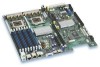
...-MHz front side bus. or 1333-MHz front side bus. Product codes S5000PALR and S5000XALR only. Up to two 45nm 2P Dual-Core Intel® Xeon® processors. Product codes S5000PALR and S5000XALR only. • Eight DIMM slots supporting stacked DDR2 533/667...Intel® Xeon® processors. Table 2 summarizes the features of : • Intel® 5000P or Intel® 5000X Memory Controller Hub (MCH) • Intel® 6321ESB I /O Controll Video Hard drive LAN Expansion Capabilities Fans Description Support for two processor fans and four system fans 2 Intel® Server Board S5000PAL...
...-MHz front side bus. or 1333-MHz front side bus. Product codes S5000PALR and S5000XALR only. Up to two 45nm 2P Dual-Core Intel® Xeon® processors. Product codes S5000PALR and S5000XALR only. • Eight DIMM slots supporting stacked DDR2 533/667...Intel® Xeon® processors. Table 2 summarizes the features of : • Intel® 5000P or Intel® 5000X Memory Controller Hub (MCH) • Intel® 6321ESB I /O Controll Video Hard drive LAN Expansion Capabilities Fans Description Support for two processor fans and four system fans 2 Intel® Server Board S5000PAL...

User Guide
Page 28
... under "Additional Information and Software." 10 Intel® Server Board S5000PAL User's Guide Processor Support for one or two Dual-Core Intel® Xeon® processors 5000 or 5100 sequence with a 1066- Up to two Quad-Core Intel® Xeon® processors 5300 sequence with a 677-, 1066-, or...MHz front side bus. Up to two 45nm next generation Quad-Core Intel® Xeon® processors. Up to two 45nm 2P Dual-Core Intel® Xeon® processors. or 1333-MHz front side bus. Product codes S5000PALR and S5000XALR only. For a complete list of qualified components, see...
... under "Additional Information and Software." 10 Intel® Server Board S5000PAL User's Guide Processor Support for one or two Dual-Core Intel® Xeon® processors 5000 or 5100 sequence with a 1066- Up to two Quad-Core Intel® Xeon® processors 5300 sequence with a 677-, 1066-, or...MHz front side bus. Up to two 45nm next generation Quad-Core Intel® Xeon® processors. Up to two 45nm 2P Dual-Core Intel® Xeon® processors. or 1333-MHz front side bus. Product codes S5000PALR and S5000XALR only. For a complete list of qualified components, see...
User Guide
Page 41
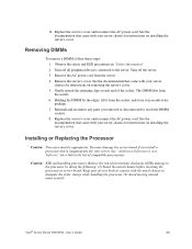
...came with your server chassis for your server chassis for instructions on removing the server's cover. 5. Installing or Replacing the Processor Caution: Processor must be appropriate: You may damage the server board if you removed or disconnected to the server. Turn off all peripheral...Holding the DIMM by doing the following: (1) Touch the metal chassis before touching the processor or server board. 11. Turn off the server. 3. Remove the server's cover. Caution: ESD and handling processors: Reduce the risk of the socket. "Intel® Server Board S5000PAL User's Guide" 23
...came with your server chassis for your server chassis for instructions on removing the server's cover. 5. Installing or Replacing the Processor Caution: Processor must be appropriate: You may damage the server board if you removed or disconnected to the server. Turn off all peripheral...Holding the DIMM by doing the following: (1) Touch the metal chassis before touching the processor or server board. 11. Turn off the server. 3. Remove the server's cover. Caution: ESD and handling processors: Reduce the risk of the socket. "Intel® Server Board S5000PAL User's Guide" 23

User Guide
Page 42
... the server's cover. 5. they are very sensitive and easily damaged. 24 "Intel® Server Board S5000PAL User's Guide" Raise the CPU load plate (see Figure 12). TP02074 Figure 12. Turn off all peripheral devices connected to the server. Locate the processor socket and raise the socket handle completely (see Figure 13). Installing the...
... the server's cover. 5. they are very sensitive and easily damaged. 24 "Intel® Server Board S5000PAL User's Guide" Raise the CPU load plate (see Figure 12). TP02074 Figure 12. Turn off all peripheral devices connected to the server. Locate the processor socket and raise the socket handle completely (see Figure 13). Installing the...

User Guide
Page 43
A B TP02076 Figure 14. Remove the protective socket cover (see Figure 14). Lower the CPU load plate and lower the socket lever completely. Removing the Socket Cover 9. "Intel® Server Board S5000PAL User's Guide" 25 7. Line up the alignment marks on the processor and the socket, and insert the processor into the socket. Note: Make sure the alignment triangle mark and the alignment triangle cutout align correctly. 8. Note: Retain the protective socket cover for use when removing a processor that will not be replaced.
A B TP02076 Figure 14. Remove the protective socket cover (see Figure 14). Lower the CPU load plate and lower the socket lever completely. Removing the Socket Cover 9. "Intel® Server Board S5000PAL User's Guide" 25 7. Line up the alignment marks on the processor and the socket, and insert the processor into the socket. Note: Make sure the alignment triangle mark and the alignment triangle cutout align correctly. 8. Note: Retain the protective socket cover for use when removing a processor that will not be replaced.

User Guide
Page 44
... heat sink has Thermal Interface Material (TIM) located on installing the server's cover. 26 "Intel® Server Board S5000PAL User's Guide" Use caution when you unpack the heat sink so you removed or disconnected to reach the processor sockets. 5. Installing the Heat Sink 4. Reinstall and reconnect any parts you do not damage the...
... heat sink has Thermal Interface Material (TIM) located on installing the server's cover. 26 "Intel® Server Board S5000PAL User's Guide" Use caution when you unpack the heat sink so you removed or disconnected to reach the processor sockets. 5. Installing the Heat Sink 4. Reinstall and reconnect any parts you do not damage the...

User Guide
Page 45
... not pull up easily, twist the heat sink again. Raise the CPU load plate. 11. If installing a replacement processor, see "Installing the Processor". Remove the processor. 12. Turn off all peripheral devices connected to break the seal between the heat sink and the... instructions on the corners of the heat sink. 7. Removing a Processor 1. Remove the server's cover. Do not force the heat sink from the server. 4. Otherwise, install the protective socket cover over the empty processor socket and reinstall the chassis cover. "Intel® Server Board S5000PAL User's Guide" 27
... not pull up easily, twist the heat sink again. Raise the CPU load plate. 11. If installing a replacement processor, see "Installing the Processor". Remove the processor. 12. Turn off all peripheral devices connected to break the seal between the heat sink and the... instructions on the corners of the heat sink. 7. Removing a Processor 1. Remove the server's cover. Do not force the heat sink from the server. 4. Otherwise, install the protective socket cover over the empty processor socket and reinstall the chassis cover. "Intel® Server Board S5000PAL User's Guide" 27

User Guide
Page 60
... cable(s) on the back of the chassis and at the AC source. • Are all cables correctly connected and secured? • Are the processors fully seated in their sockets on the server board? • Are all standoffs in the proper location and not touching any components, causing a potential... system list. If the problem you press the system power on/off switch on the front panel to the tested component lists. 42 Intel® Server Board S5000PAL User's Guide First Steps Checklist • Is AC power available at initial system startup are no conflicts-for 200-240V ? •...
... cable(s) on the back of the chassis and at the AC source. • Are all cables correctly connected and secured? • Are the processors fully seated in their sockets on the server board? • Are all standoffs in the proper location and not touching any components, causing a potential... system list. If the problem you press the system power on/off switch on the front panel to the tested component lists. 42 Intel® Server Board S5000PAL User's Guide First Steps Checklist • Is AC power available at initial system startup are no conflicts-for 200-240V ? •...

User Guide
Page 62
... the memory DIMMs and re-seat them . • Make sure the chassis standoffs are problems with the system requirements. • Make sure the processor(s) have a power switch on ? • Remove all add-in the order given. If you cannot correct the problem, contact your system has one... requirements. • Remove the processor(s) and re-seat them . • Make sure the processor(s) comply with application software. • The bootable CD-ROM is it turned on the back of the server board and cause a short. 44 Intel® Server Board S5000PAL User's Guide Try the solutions ...
... the memory DIMMs and re-seat them . • Make sure the chassis standoffs are problems with the system requirements. • Make sure the processor(s) have a power switch on ? • Remove all add-in the order given. If you cannot correct the problem, contact your system has one... requirements. • Remove the processor(s) and re-seat them . • Make sure the processor(s) comply with application software. • The bootable CD-ROM is it turned on the back of the server board and cause a short. 44 Intel® Server Board S5000PAL User's Guide Try the solutions ...

User Guide
Page 63
... is useful for changes to the system requirements. • Remove the processor(s) and re-seat them . • Make sure the processor(s) comply with the system requirements. • Make sure the processor(s) have been populated according to take effect. 4. Intel® Server Board S5000PAL User's Guide 45 Verify that the video controller board is functioning. •...
... is useful for changes to the system requirements. • Remove the processor(s) and re-seat them . • Make sure the processor(s) comply with the system requirements. • Make sure the processor(s) have been populated according to take effect. 4. Intel® Server Board S5000PAL User's Guide 45 Verify that the video controller board is functioning. •...

User Guide
Page 69
.... Chipset control failure. Table 9. Reseat or replace the failed processor. In a two-processor system, make sure the processors are provided if an Intel® Remote Management Module is installed. Error Beep Codes Generated by Intel® Remote Management Module Number of Beeps 1 1-5-1-1 1-5-2-1 ...processor. Power control failure. No processor is installed or the CPU 1 socket is empty. Reseat or replace the failed processor. Processor configuration error or CPU 1 socket is empty. In addition to Take Control panel CMOS clear has been initiated. Intel® Server Board S5000PAL...
.... Chipset control failure. Table 9. Reseat or replace the failed processor. In a two-processor system, make sure the processors are provided if an Intel® Remote Management Module is installed. Error Beep Codes Generated by Intel® Remote Management Module Number of Beeps 1 1-5-1-1 1-5-2-1 ...processor. Power control failure. No processor is installed or the CPU 1 socket is empty. Reseat or replace the failed processor. Processor configuration error or CPU 1 socket is empty. In addition to Take Control panel CMOS clear has been initiated. Intel® Server Board S5000PAL...

User Guide
Page 72
... OFF OFF 0x25h OFF 0x26h 0x27h 0x28h OFF OFF G OFF OFF R OFF OFF A OFF G R OFF G A Power-on initialization of the host processor (bootstrap processor) Host processor cache initialization (including AP) Starting application processor initialization SMM initialization OFF R G Initializing a chipset component OFF A OFF A G R G R G A G A OFF R OFF G OFF G OFF ... the memory controller Optimizing memory controller settings Initializing memory, such as ECC init Testing memory 54 Intel® Server Board S5000PAL User's Guide Diagnostic LED Placement Diagram Table 11.
... OFF OFF 0x25h OFF 0x26h 0x27h 0x28h OFF OFF G OFF OFF R OFF OFF A OFF G R OFF G A Power-on initialization of the host processor (bootstrap processor) Host processor cache initialization (including AP) Starting application processor initialization SMM initialization OFF R G Initializing a chipset component OFF A OFF A G R G R G A G A OFF R OFF G OFF G OFF ... the memory controller Optimizing memory controller settings Initializing memory, such as ECC init Testing memory 54 Intel® Server Board S5000PAL User's Guide Diagnostic LED Placement Diagram Table 11.


