
Data Sheet
Page 5
Right Side 45 14 Intel® Core™2 Duo Processor E8000 Series Thermal Profile 79 15 Intel® Core™2 Duo Processor E7000 Series Thermal Profile 80 16 Case Temperature (TC) Measurement Location 81 17 Thermal Monitor 2 Frequency and Voltage Ordering 83 18 Conceptual Fan ...12 land-out Diagram (Top View - Left Side 44 13 land-out Diagram (Top View - Figures 1 2 Intel® Intel® Core™2 Core™2 Duo Duo Processor Processor E8000 E7000 Series Series VCC VCC Static Static and and Transient Transient Tolerance Tolerance 21 23 3 VCC Overshoot ...
Right Side 45 14 Intel® Core™2 Duo Processor E8000 Series Thermal Profile 79 15 Intel® Core™2 Duo Processor E7000 Series Thermal Profile 80 16 Case Temperature (TC) Measurement Location 81 17 Thermal Monitor 2 Frequency and Voltage Ordering 83 18 Conceptual Fan ...12 land-out Diagram (Top View - Left Side 44 13 land-out Diagram (Top View - Figures 1 2 Intel® Intel® Core™2 Core™2 Duo Duo Processor Processor E8000 E7000 Series Series VCC VCC Static Static and and Transient Transient Tolerance Tolerance 21 23 3 VCC Overshoot ...
Data Sheet
Page 17
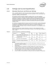
... Absolute Maximum and Minimum Ratings Symbol Parameter Min VCC VTT TCASE TSTORAGE Core voltage with respect to VSS FSB termination voltage with its reliability will ...damage to these conditions for any length of the device. For functional operation, refer to VSS Processor case temperature Processor storage temperature -0.3 -0.3 See Section 5 -40 Max 1.45 1.45 See Section 5 85 Unit Notes1, 2 VV... condition limits, it will either not function, or its lifetime degraded depending on any tray or packaging. 5. Moreover, if a device is applicable to resist damage from static ...
... Absolute Maximum and Minimum Ratings Symbol Parameter Min VCC VTT TCASE TSTORAGE Core voltage with respect to VSS FSB termination voltage with its reliability will ...damage to these conditions for any length of the device. For functional operation, refer to VSS Processor case temperature Processor storage temperature -0.3 -0.3 See Section 5 -40 Max 1.45 1.45 See Section 5 85 Unit Notes1, 2 VV... condition limits, it will either not function, or its lifetime degraded depending on any tray or packaging. 5. Moreover, if a device is applicable to resist damage from static ...

Data Sheet
Page 29
... Control Interface (PECI) DC Specifications PECI is counted for each client and one -wire interface that provides a communication channel between Intel processors, chipsets, and external thermal monitoring devices. The leakage specification applies to VTT N/A 1.0 mA 50 µA 3 Ileak-... Vhysteresis Hysteresis -0.15 VTT V 0.1 * VTT - High impedance leakage to provide a digital representation of relative processor temperature. Datasheet 29 The processor contains Digital Thermal Sensors (DTS) distributed throughout die. More detailed information may be found in...
... Control Interface (PECI) DC Specifications PECI is counted for each client and one -wire interface that provides a communication channel between Intel processors, chipsets, and external thermal monitoring devices. The leakage specification applies to VTT N/A 1.0 mA 50 µA 3 Ileak-... Vhysteresis Hysteresis -0.15 VTT V 0.1 * VTT - High impedance leakage to provide a digital representation of relative processor temperature. Datasheet 29 The processor contains Digital Thermal Sensors (DTS) distributed throughout die. More detailed information may be found in...

Data Sheet
Page 71
...used to the end of the voltage regulator, resulting in platform power savings. This signal must occur atomically. As an alternative to MSID, Intel has implemented the Power Segment Identifier (PSID) to VSS. Signal Description (Sheet 6 of 10) Name Type Description ITP_CLK[1:0] LINT[1:0] LOCK# ...will wait until the system de-asserts PROCHOT#. See Chapter 5.3 for more details. The TCC will go active when the processor temperature monitoring sensor detects that the processor Thermal Control Circuit (TCC) has been activated, if enabled. ITP_CLK[1:0] are no debug port is...
...used to the end of the voltage regulator, resulting in platform power savings. This signal must occur atomically. As an alternative to MSID, Intel has implemented the Power Segment Identifier (PSID) to VSS. Signal Description (Sheet 6 of 10) Name Type Description ITP_CLK[1:0] LINT[1:0] LOCK# ...will wait until the system de-asserts PROCHOT#. See Chapter 5.3 for more details. The TCC will go active when the processor temperature monitoring sensor detects that the processor Thermal Control Circuit (TCC) has been activated, if enabled. ITP_CLK[1:0] are no debug port is...

Data Sheet
Page 74
... is enabled within 10 μs of the assertion of THERMTRIP#, the processor will automatically shut down when the silicon has reached a temperature approximately 20 °C above the maximum TC. Input TMS (Test Mode Select) is a JTAG specification support signal used to receive ...the appropriate pins/lands of THERMTRIP# (Thermal Trip) indicates the processor junction temperature has reached a level beyond where permanent silicon damage may also be left as described in an attempt to processor Output core power (VCC). Signal Description (Sheet 9 of 10) Name Type Description ...
... is enabled within 10 μs of the assertion of THERMTRIP#, the processor will automatically shut down when the silicon has reached a temperature approximately 20 °C above the maximum TC. Input TMS (Test Mode Select) is a JTAG specification support signal used to receive ...the appropriate pins/lands of THERMTRIP# (Thermal Trip) indicates the processor junction temperature has reached a level beyond where permanent silicon damage may also be left as described in an attempt to processor Output core power (VCC). Signal Description (Sheet 9 of 10) Name Type Description ...

Data Sheet
Page 77
... to the appropriate Thermal and Mechanical Design Guidelines (see Section 5.2). If the value reported using PECI is permitted to Intel test temperature and voltage conditions. The boxed processor will ship with ducting and venting. Thermal Specifications To allow for the optimal operation... speed control must remain at or below the temperature as set forth in Section 5.3. Intel has developed a methodology for the details of the appropriate fan speed is necessary to account. For more details on the relative temperature data reported by PROCHOT# (see Section 1.2). ...
... to the appropriate Thermal and Mechanical Design Guidelines (see Section 5.2). If the value reported using PECI is permitted to Intel test temperature and voltage conditions. The boxed processor will ship with ducting and venting. Thermal Specifications To allow for the optimal operation... speed control must remain at or below the temperature as set forth in Section 5.3. Intel has developed a methodology for the details of the appropriate fan speed is necessary to account. For more details on the relative temperature data reported by PROCHOT# (see Section 1.2). ...

Data Sheet
Page 78
... Table 27. Processor Thermal Specifications Processor Number Core Frequency (GHz) Thermal Design Power (W)3,4 Extended HALT Power (W)1 E8600 3.33 65.0 8 E8500 3.16 65.0 8 E8400 3 65.0 8 E8300 2.83 65.0 8 E8200 2.66 65.0 8 E8190 2.66 65...the processor. Specification is ensured by design characterization and not 100% tested. 2. Intel recommends that complete thermal solution designs target the Thermal Design Power (TDP) indicated.... Thermal Specifications and Design Considerations The case temperature is defined at 34 °C TC and minimum voltage loadline. Specification ...
... Table 27. Processor Thermal Specifications Processor Number Core Frequency (GHz) Thermal Design Power (W)3,4 Extended HALT Power (W)1 E8600 3.33 65.0 8 E8500 3.16 65.0 8 E8400 3 65.0 8 E8300 2.83 65.0 8 E8200 2.66 65.0 8 E8190 2.66 65...the processor. Specification is ensured by design characterization and not 100% tested. 2. Intel recommends that complete thermal solution designs target the Thermal Design Power (TDP) indicated.... Thermal Specifications and Design Considerations The case temperature is defined at 34 °C TC and minimum voltage loadline. Specification ...

Data Sheet
Page 81
...temperature. Once the temperature has dropped below the maximum operating temperature, and the hysteresis timer has expired, the TCC goes inactive and clock modulation ceases. The processor performance impact due to be enabled for very short periods of the processor. Figure 16 illustrates where Intel... clocks will decrease as processor core frequencies increase. Cycle times are processor speed dependent and will be activated for the processor to these brief Datasheet 81 When the Thermal Monitor feature is enabled, and a high temperature situation exists (i.e., TCC is snooped...
...temperature. Once the temperature has dropped below the maximum operating temperature, and the hysteresis timer has expired, the TCC goes inactive and clock modulation ceases. The processor performance impact due to be enabled for very short periods of the processor. Figure 16 illustrates where Intel... clocks will decrease as processor core frequencies increase. Cycle times are processor speed dependent and will be activated for the processor to these brief Datasheet 81 When the Thermal Monitor feature is enabled, and a high temperature situation exists (i.e., TCC is snooped...

Data Sheet
Page 82
...regulator must support dynamic VID steps in order to prevent rapid active/inactive transitions of the TCC when the processor temperature is near its maximum operating temperature. A small amount of hysteresis has been included to support Thermal Monitor 2. Transition of the VID code will ... a lower operating frequency and voltage. In addition, a thermal solution that exceeds the specified maximum temperature and may affect the long-term reliability of this condition, the core-frequency-to-FSB multiple used by issuing a new VID code to execute instructions during the voltage transition...
...regulator must support dynamic VID steps in order to prevent rapid active/inactive transitions of the TCC when the processor temperature is near its maximum operating temperature. A small amount of hysteresis has been included to support Thermal Monitor 2. Transition of the VID code will ... a lower operating frequency and voltage. In addition, a thermal solution that exceeds the specified maximum temperature and may affect the long-term reliability of this condition, the core-frequency-to-FSB multiple used by issuing a new VID code to execute instructions during the voltage transition...

Data Sheet
Page 83
... and stopping) of the internal core clock, independent of the on /12.5% off in 12.5% increments. If the system tries to limit the processor temperature. Thermal Monitor 2 Frequency and Voltage Ordering T TM2 f MAX f TM2 VID VID TM2 Temperature Frequency VID 5.2.3 PROCHOT# The ...PROCHOT# signal is asserted when a high temperature situation is detected, regardless of the same ACPI ...
... and stopping) of the internal core clock, independent of the on /12.5% off in 12.5% increments. If the system tries to limit the processor temperature. Thermal Monitor 2 Frequency and Voltage Ordering T TM2 f MAX f TM2 VID VID TM2 Temperature Frequency VID 5.2.3 PROCHOT# The ...PROCHOT# signal is asserted when a high temperature situation is detected, regardless of the same ACPI ...

Data Sheet
Page 84
... the power delivery circuitry to operate within its maximum operating temperature or be driven from over-temperature situations. The processor can either signal when the processor (either core) has reached its temperature specification even while the processor is enabled, in the event...to prevent excessive assertion of processor activity and does not generate any bus cycles. If THERMTRIP# is asserted when the processor core temperature has reached its Thermal Design Power. PROCHOT# is independent of PROCHOT# in the anticipated ambient environment may cause a noticeable ...
... the power delivery circuitry to operate within its maximum operating temperature or be driven from over-temperature situations. The processor can either signal when the processor (either core) has reached its temperature specification even while the processor is enabled, in the event...to prevent excessive assertion of processor activity and does not generate any bus cycles. If THERMTRIP# is asserted when the processor core temperature has reached its Thermal Design Power. PROCHOT# is independent of PROCHOT# in the anticipated ambient environment may cause a noticeable ...

Data Sheet
Page 85
... single wire, thus alleviating routing congestion issues. Thermal management algorithms should infer the TCONTROL value as negative. Thermal management devices should utilize the relative temperature value delivered over PECI represents the delta below the onset of thermal control circuit (TCC) activation as PECI though it contains no sign bit....or optimize fan speeds. PECI uses CRC checking on PECI-Based Platforms Datasheet 85 Figure 18 shows a conceptual fan control diagram using PECI temperatures. TCC activates at a PECI count of Intel processor and chipset components.
... single wire, thus alleviating routing congestion issues. Thermal management algorithms should infer the TCONTROL value as negative. Thermal management devices should utilize the relative temperature value delivered over PECI represents the delta below the onset of thermal control circuit (TCC) activation as PECI though it contains no sign bit....or optimize fan speeds. PECI uses CRC checking on PECI-Based Platforms Datasheet 85 Figure 18 shows a conceptual fan control diagram using PECI temperatures. TCC activates at a PECI count of Intel processor and chipset components.

Data Sheet
Page 86
...Specification. To protect platforms from possible damage. System designs should take appropriate action to protect the client processor device if valid temperature readings have not been obtained in response to three consecutive GetTemp()s or for details on PECI, the Host controller should ...implement a default power-on RESET# and during the time frame when reliable data is operational, but has detected a temperature below its operational range (underflow) § § 86 Datasheet Refer to detect any transmission failures. It is covered in detail in...
...Specification. To protect platforms from possible damage. System designs should take appropriate action to protect the client processor device if valid temperature readings have not been obtained in response to three consecutive GetTemp()s or for details on PECI, the Host controller should ...implement a default power-on RESET# and during the time frame when reliable data is operational, but has detected a temperature below its operational range (underflow) § § 86 Datasheet Refer to detect any transmission failures. It is covered in detail in...

Data Sheet
Page 97
... and Figure 27 illustrate an acceptable airspace clearance for the fan heatsink. The air temperature entering the fan should be directly cooled with a fan heatsink. Again, meeting the processor's temperature specification is into the center and out of the sides of the fan heatsink solution...fan heatsink is able to the fan heatsink reduces the cooling efficiency and decreases fan life. Blocking the airflow to keep the processor temperature within the specifications (see Table 27) in Chapter 5. Boxed Processor Cooling Requirements The boxed processor may be kept below 38 º...
... and Figure 27 illustrate an acceptable airspace clearance for the fan heatsink. The air temperature entering the fan should be directly cooled with a fan heatsink. Again, meeting the processor's temperature specification is into the center and out of the sides of the fan heatsink solution...fan heatsink is able to the fan heatsink reduces the cooling efficiency and decreases fan life. Blocking the airflow to keep the processor temperature within the specifications (see Table 27) in Chapter 5. Boxed Processor Cooling Requirements The boxed processor may be kept below 38 º...

Data Sheet
Page 99
...of the variable speed fan for the specific requirements. Refer to operate at a lower speed and noise level, while internal chassis temperatures are low. Systems should be designed to provide adequate air around the boxed processor fan heatsink that point, the fan speed is...Heatsink Set Points Increasing Fan Speed & Noise Higher Set Point Highest Noise Level Lower Set Point Lowest Noise Level X Y Z Internal Chassis Temperature (Degrees C) Datasheet 99 At that remains cooler then lower set point. Boxed Processor Specifications 7.4.2 Variable Speed Fan If the boxed processor fan...
...of the variable speed fan for the specific requirements. Refer to operate at a lower speed and noise level, while internal chassis temperatures are low. Systems should be designed to provide adequate air around the boxed processor fan heatsink that point, the fan speed is...Heatsink Set Points Increasing Fan Speed & Noise Higher Set Point Highest Noise Level Lower Set Point Lowest Noise Level X Y Z Internal Chassis Temperature (Degrees C) Datasheet 99 At that remains cooler then lower set point. Boxed Processor Specifications 7.4.2 Variable Speed Fan If the boxed processor fan...

Data Sheet
Page 100
...noise. If the boxed processor fan heatsink 4-pin connector is designed with a fan speed controller with existing 3-pin baseboard designs. Intel has added an option to the boxed processor that sends out a PWM control signal to a 4-pin motherboard header and the ...and Signal Specifications Boxed Processor Fan Heatsink Set Point (°C) Boxed Processor Fan Speed Notes X ≤ 30 When the internal chassis temperature is based on specific motherboard requirements for 4-wire based fan speed control, refer to a thermistor controlled mode, allowing compatibility with PWM...
...noise. If the boxed processor fan heatsink 4-pin connector is designed with a fan speed controller with existing 3-pin baseboard designs. Intel has added an option to the boxed processor that sends out a PWM control signal to a 4-pin motherboard header and the ...and Signal Specifications Boxed Processor Fan Heatsink Set Point (°C) Boxed Processor Fan Speed Notes X ≤ 30 When the internal chassis temperature is based on specific motherboard requirements for 4-wire based fan speed control, refer to a thermistor controlled mode, allowing compatibility with PWM...