
Technical Product Specification
Page 7
... Description 1.1 Overview 11 1.1.1 Feature Summary 11 1.1.2 Board Layout (Top 13 1.1.3 Board Layout (Bottom 15 1.1.4 Block Diagram 17 1.2 Online Support 18 1.3 Processor 18 1.4 System Memory 19 1.4.1 Memory Configurations 20 1.5 Intel® QS77 Express Chipset 22 1.5.1 Direct Media Interface (DMI 22 1.5.2 Display Interfaces 22 1.6 Graphics Subsystem 22 1.6.1 Integrated Graphics 22 1.6.2 USB 24 1.7 SATA Interface 24...
... Description 1.1 Overview 11 1.1.1 Feature Summary 11 1.1.2 Board Layout (Top 13 1.1.3 Board Layout (Bottom 15 1.1.4 Block Diagram 17 1.2 Online Support 18 1.3 Processor 18 1.4 System Memory 19 1.4.1 Memory Configurations 20 1.5 Intel® QS77 Express Chipset 22 1.5.1 Direct Media Interface (DMI 22 1.5.2 Display Interfaces 22 1.6 Graphics Subsystem 22 1.6.1 Integrated Graphics 22 1.6.2 USB 24 1.7 SATA Interface 24...

Technical Product Specification
Page 8
Intel Desktop Board D33217GKE Technical Product Specification 2 Technical Reference 2.1 Memory Resources 35 2.1.1 Addressable Memory 35 2.1.2 Memory Map 37 2.2 Connectors and Headers 37 2.2.1 Back Panel Connectors 38 2.2.2 Connectors and Headers (Bottom 39...Fan Header Current Capability 50 2.6 Thermal Considerations 50 2.7 Reliability 53 2.8 Environmental 53 3 Overview of BIOS Features 3.1 Introduction 55 3.2 BIOS Flash Memory Organization 56 3.3 System Management BIOS (SMBIOS 56 3.4 Legacy USB Support 56 3.5 BIOS Updates 57 3.5.1 Language Support 57 3.5.2 Custom Splash Screen ...
Intel Desktop Board D33217GKE Technical Product Specification 2 Technical Reference 2.1 Memory Resources 35 2.1.1 Addressable Memory 35 2.1.2 Memory Map 37 2.2 Connectors and Headers 37 2.2.1 Back Panel Connectors 38 2.2.2 Connectors and Headers (Bottom 39...Fan Header Current Capability 50 2.6 Thermal Considerations 50 2.7 Reliability 53 2.8 Environmental 53 3 Overview of BIOS Features 3.1 Introduction 55 3.2 BIOS Flash Memory Organization 56 3.3 System Management BIOS (SMBIOS 56 3.4 Legacy USB Support 56 3.5 BIOS Updates 57 3.5.1 Language Support 57 3.5.2 Custom Splash Screen ...
Technical Product Specification
Page 9
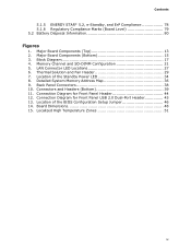
Memory Channel and SO-DIMM Configuration 21 5. Location of the Standby Power LED 34 8. Back Panel Connectors 38 10. Board Dimensions 48 15. Major Board Components (... 44 12. Thermal Solution and Fan Header 29 7. Connectors and Headers (Bottom 39 11. Location of the BIOS Configuration Setup Jumper 46 14. Detailed System Memory Address Map 36 9. Connection Diagram for Front Panel USB 2.0 Dual-Port Header 45 13. Contents 5.1.5 ENERGY STAR* 5.2, e-Standby, and ErP Compliance 78 5.1.6 Regulatory Compliance Marks...
Memory Channel and SO-DIMM Configuration 21 5. Location of the Standby Power LED 34 8. Back Panel Connectors 38 10. Board Dimensions 48 15. Major Board Components (... 44 12. Thermal Solution and Fan Header 29 7. Connectors and Headers (Bottom 39 11. Location of the BIOS Configuration Setup Jumper 46 14. Detailed System Memory Address Map 36 9. Connection Diagram for Front Panel USB 2.0 Dual-Port Header 45 13. Contents 5.1.5 ENERGY STAR* 5.2, e-Standby, and ErP Compliance 78 5.1.6 Regulatory Compliance Marks...

Technical Product Specification
Page 10
Feature Summary 11 2. Supported Memory Configurations 19 5. Front Panel Header 43 15. Tcontrol Values for Components 52 19. Port 80h POST Code ...LED 44 16. Regulatory Compliance Marks 79 x Components Shown in Figure 2 16 4. Effects of Pressing the Power Switch 30 7. System Memory Map 37 10. Fan Header Current Capability 50 18. Boot Device Menu Options 59 23. BIOS Error Messages 63 27. Wake-up ...Express Full-Mini Card Connector 41 12. Port 80h POST Codes 65 29. Safety Standards 71 31. Intel Desktop Board D33217GKE Technical Product Specification Tables 1.
Feature Summary 11 2. Supported Memory Configurations 19 5. Front Panel Header 43 15. Tcontrol Values for Components 52 19. Port 80h POST Code ...LED 44 16. Regulatory Compliance Marks 79 x Components Shown in Figure 2 16 4. Effects of Pressing the Power Switch 30 7. System Memory Map 37 10. Fan Header Current Capability 50 18. Boot Device Menu Options 59 23. BIOS Error Messages 63 27. Wake-up ...Express Full-Mini Card Connector 41 12. Port 80h POST Codes 65 29. Safety Standards 71 31. Intel Desktop Board D33217GKE Technical Product Specification Tables 1.
Technical Product Specification
Page 11
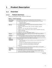
...60 millimeters by 101.60 millimeters) • Soldered-down Intel® Core™ i3-3217U processor with up to 17 W TDP ― Integrated graphics ― Integrated memory controller • Two 204-pin DDR3 SDRAM Small Outline Dual Inline Memory Module (SO-DIMM) sockets • Support for DDR3 ...• One PCI Express Half-Mini Card connector • One PCI Express Full-Mini Card connector • Intel® BIOS resident in the Serial Peripheral Interface (SPI) Flash device • Support for 1.35 V low voltage JEDEC memory Intel® QS77 Express Chipset consisting of the board.
...60 millimeters by 101.60 millimeters) • Soldered-down Intel® Core™ i3-3217U processor with up to 17 W TDP ― Integrated graphics ― Integrated memory controller • Two 204-pin DDR3 SDRAM Small Outline Dual Inline Memory Module (SO-DIMM) sockets • Support for DDR3 ...• One PCI Express Half-Mini Card connector • One PCI Express Full-Mini Card connector • Intel® BIOS resident in the Serial Peripheral Interface (SPI) Flash device • Support for 1.35 V low voltage JEDEC memory Intel® QS77 Express Chipset consisting of the board.
Technical Product Specification
Page 18
... World Wide Web site: http://www.intel.com/products/motherboard/index.htm http://www.intel.com/p/en_US/support?iid=hdr+support http://ark.intel.com Chipset information BIOS and driver updates Tested memory Integration information http://www.intel.com/products/desktop/chipsets/index.htm http://downloadcenter.intel.com http://www.intel.com/support/motherboards/desktop/sb/CS025414...
... World Wide Web site: http://www.intel.com/products/motherboard/index.htm http://www.intel.com/p/en_US/support?iid=hdr+support http://ark.intel.com Chipset information BIOS and driver updates Tested memory Integration information http://www.intel.com/products/desktop/chipsets/index.htm http://downloadcenter.intel.com http://www.intel.com/support/motherboards/desktop/sb/CS025414...
Technical Product Specification
Page 19
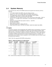
...x 16 4 2 GB 1 Gb 128 M x 8 16 F 4 GB 2 Gb 256 M x 8 16 8 GB 4 Gb 512 M x 8 16 Note: System memory configurations are based on the total amount of addressable memory. • Minimum recommended total system memory: 1024 MB • Non-ECC SO-DIMMs • Serial Presence Detect • XMP profile support for 1.35 V Low... 1333 MHz, and DDR3 1066 MHz SDRAM SO-DIMMs NOTE To be fully compliant with all applicable DDR SDRAM memory specifications, the board should be impacted or the SO-DIMMs may not function under the determined frequency. Table 5. Refer to accurately ...
...x 16 4 2 GB 1 Gb 128 M x 8 16 F 4 GB 2 Gb 256 M x 8 16 8 GB 4 Gb 512 M x 8 16 Note: System memory configurations are based on the total amount of addressable memory. • Minimum recommended total system memory: 1024 MB • Non-ECC SO-DIMMs • Serial Presence Detect • XMP profile support for 1.35 V Low... 1333 MHz, and DDR3 1066 MHz SDRAM SO-DIMMs NOTE To be fully compliant with all applicable DDR SDRAM memory specifications, the board should be impacted or the SO-DIMMs may not function under the determined frequency. Table 5. Refer to accurately ...
Technical Product Specification
Page 20
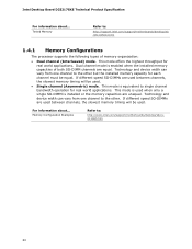
... to single channel bandwidth operation for real world applications. Technology and device width can vary from one channel to : http://support.intel.com/support/motherboards/desktop/sb /CS-025414.htm 1.4.1 Memory Configurations The processor supports the following types of both SO-DIMM channels are unequal. If different speed SO-DIMMs are used...
... to single channel bandwidth operation for real world applications. Technology and device width can vary from one channel to : http://support.intel.com/support/motherboards/desktop/sb /CS-025414.htm 1.4.1 Memory Configurations The processor supports the following types of both SO-DIMM channels are unequal. If different speed SO-DIMMs are used...

Technical Product Specification
Page 21
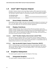
Memory Channel and SO-DIMM Configuration 21 Product Description Figure 4 illustrates the memory channel and SO-DIMM configuration. Figure 4.
Memory Channel and SO-DIMM Configuration 21 Product Description Figure 4 illustrates the memory channel and SO-DIMM configuration. Figure 4.
Technical Product Specification
Page 22
...display interface. 1.5.2.1 Intel® Flexible Display Interconnect (Intel® FDI) Intel FDI connects the display engine in the display engine of the processor and sent to the processor and the USB, SATA, LPC, LAN, and PCI Express interfaces. The processor houses the memory interface, display planes,... and pipes while the PCH has transcoder and display interface or ports. The PCH receives the display data over Intel® Flexible Display Interface (Intel® FDI) and transcodes the data as per the...
...display interface. 1.5.2.1 Intel® Flexible Display Interconnect (Intel® FDI) Intel FDI connects the display engine in the display engine of the processor and sent to the processor and the USB, SATA, LPC, LAN, and PCI Express interfaces. The processor houses the memory interface, display planes,... and pipes while the PCH has transcoder and display interface or ports. The PCH receives the display data over Intel® Flexible Display Interface (Intel® FDI) and transcodes the data as per the...

Technical Product Specification
Page 23
Each port is compatible with 4 GB and above system memory configuration 1.6.1.2 Video Memory Allocation Intel® Dynamic Video Memory Technology (DVMT) is a method for dynamically allocating system memory for other uses. 1.6.1.3 High Definition Multimedia Interface* (HDMI*) The two HDMI ...the dynamically allocated portion of lossless audio formats such as graphics memory to balance 2D/3D graphics and system performance. Product Description 1.6.1.1 Intel® High Definition (Intel® HD) Graphics The Intel HD graphics controller features the following audio technologies are not ...
Each port is compatible with 4 GB and above system memory configuration 1.6.1.2 Video Memory Allocation Intel® Dynamic Video Memory Technology (DVMT) is a method for dynamically allocating system memory for other uses. 1.6.1.3 High Definition Multimedia Interface* (HDMI*) The two HDMI ...the dynamically allocated portion of lossless audio formats such as graphics memory to balance 2D/3D graphics and system performance. Product Description 1.6.1.1 Intel® High Definition (Intel® HD) Graphics The Intel HD graphics controller features the following audio technologies are not ...
Technical Product Specification
Page 25
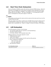
Product Description 1.8 Real-Time Clock Subsystem A coin-cell battery (CR2032) powers the real-time clock and CMOS memory. NOTE If the battery and AC power fail, date and time values will be reset and the user will be accurate. When the voltage drops...Figure 1 on page 13 shows the location of the battery. 1.9 LAN Subsystem The LAN subsystem consists of the following: • Intel 82579V Gigabit Ethernet Controller (10/100/1000 Mb/s) • Intel QS77 Express Chipset • RJ-45 LAN connector with integrated status LEDs Additional features of the LAN subsystem include: • CSMA...
Product Description 1.8 Real-Time Clock Subsystem A coin-cell battery (CR2032) powers the real-time clock and CMOS memory. NOTE If the battery and AC power fail, date and time values will be reset and the user will be accurate. When the voltage drops...Figure 1 on page 13 shows the location of the battery. 1.9 LAN Subsystem The LAN subsystem consists of the following: • Intel 82579V Gigabit Ethernet Controller (10/100/1000 Mb/s) • Intel QS77 Express Chipset • RJ-45 LAN connector with integrated status LEDs Additional features of the LAN subsystem include: • CSMA...
Technical Product Specification
Page 28
...Management Subsystem The hardware management features enable the board to be compatible with the Wired for Management (WfM) Specification Refer to www.intel.com/design/archives/wfm/ 1.10.1 Hardware Monitoring The hardware monitoring and fan control subsystem is based on a Nuvoton NPCE791C embedded ...: • Processor and system ambient temperature monitoring • Chassis fan speed monitoring • Voltage monitoring of +12 V, +5 V, +3.3 V, Memory Vcc (V_SM), +Vccp, PCH Vcc • SMBus interface 1.10.2 Fan Monitoring Fan monitoring can be implemented using third-party software. 28
...Management Subsystem The hardware management features enable the board to be compatible with the Wired for Management (WfM) Specification Refer to www.intel.com/design/archives/wfm/ 1.10.1 Hardware Monitoring The hardware monitoring and fan control subsystem is based on a Nuvoton NPCE791C embedded ...: • Processor and system ambient temperature monitoring • Chassis fan speed monitoring • Voltage monitoring of +12 V, +5 V, +3.3 V, Memory Vcc (V_SM), +Vccp, PCH Vcc • SMBus interface 1.10.2 Fan Monitoring Fan monitoring can be implemented using third-party software. 28
Technical Product Specification
Page 35
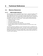
...; PCI Express configuration space (256 MB) • PCH base address registers PCI Express ports (up to reclaim the physical memory overlapped by the memory mapped I /O that is no overlap of usable DRAM boundary to the 4 GB boundary to system address space being allocated ... The board provides the capability to 256 MB) • Memory-mapped I /O logical address space. 2 Technical Reference 2.1 Memory Resources 2.1.1 Addressable Memory The board utilizes 16 GB of the system memory map. The board remaps physical memory from the top of system addresses. 35 Typically the address space...
...; PCI Express configuration space (256 MB) • PCH base address registers PCI Express ports (up to reclaim the physical memory overlapped by the memory mapped I /O that is no overlap of usable DRAM boundary to the 4 GB boundary to system address space being allocated ... The board provides the capability to 256 MB) • Memory-mapped I /O logical address space. 2 Technical Reference 2.1 Memory Resources 2.1.1 Addressable Memory The board utilizes 16 GB of the system memory map. The board remaps physical memory from the top of system addresses. 35 Typically the address space...

Technical Product Specification
Page 37
...). The connectors and headers can be divided into these connectors or headers to power devices external to the computer's chassis. Video memory and BIOS Extended BIOS data (movable by the external devices could cause damage to the board. This section describes the board's ...connectors and headers. System Memory Map Address Range (decimal) Address Range (hex) 1024 K - 16777216 K 100000 - 400000000 960 K - 1024 K F0000 - Furthermore, improper connection ...
...). The connectors and headers can be divided into these connectors or headers to power devices external to the computer's chassis. Video memory and BIOS Extended BIOS data (movable by the external devices could cause damage to the board. This section describes the board's ...connectors and headers. System Memory Map Address Range (decimal) Address Range (hex) 1024 K - 16777216 K 100000 - 400000000 960 K - 1024 K F0000 - Furthermore, improper connection ...
Technical Product Specification
Page 55
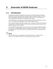
NOTE The maintenance menu is displayed only when the board is in the Serial Peripheral Interface Flash Memory (SPI Flash) and can be updated using a disk-based program. Section 2.3 on page 46 shows how to configure mode and the computer is set to .... 55 The BIOS displays a message during POST identifying the type of BIOS Features 3.1 Introduction The board uses a Intel Visual BIOS that is accessed by pressing the key after the Power-On Self-Test (POST) memory test begins and before the operating system boot begins. The initial production BIOSs are identified as GKPPT10H...
NOTE The maintenance menu is displayed only when the board is in the Serial Peripheral Interface Flash Memory (SPI Flash) and can be updated using a disk-based program. Section 2.3 on page 46 shows how to configure mode and the computer is set to .... 55 The BIOS displays a message during POST identifying the type of BIOS Features 3.1 Introduction The board uses a Intel Visual BIOS that is accessed by pressing the key after the Power-On Self-Test (POST) memory test begins and before the operating system boot begins. The initial production BIOSs are identified as GKPPT10H...
Technical Product Specification
Page 56
...BIOS revision level • Fixed-system data, such as peripherals, serial numbers, and asset tags • Resource data, such as memory size, cache size, and processor speed • Dynamic data, such as follows: 1. POST begins. 3. Legacy USB support is ...and configure the BIOS Setup program and the maintenance menu. 4. Intel Desktop Board D33217GKE Technical Product Specification 3.2 BIOS Flash Memory Organization The Serial Peripheral Interface Flash Memory (SPI Flash) includes a 64 Mb (8192 KB) flash memory device. 3.3 System Management BIOS (SMBIOS) SMBIOS is the Management...
...BIOS revision level • Fixed-system data, such as peripherals, serial numbers, and asset tags • Resource data, such as memory size, cache size, and processor speed • Dynamic data, such as follows: 1. POST begins. 3. Legacy USB support is ...and configure the BIOS Setup program and the maintenance menu. 4. Intel Desktop Board D33217GKE Technical Product Specification 3.2 BIOS Flash Memory Organization The Serial Peripheral Interface Flash Memory (SPI Flash) includes a 64 Mb (8192 KB) flash memory device. 3.3 System Management BIOS (SMBIOS) SMBIOS is the Management...

Technical Product Specification
Page 57
...desktop/sb /CS-022312.htm 3.5.1 Language Support The BIOS Setup program and help messages are available on the Web. • Intel® Flash Memory Update Utility, which enables automated updating while in the Windows environment. Both utilities verify that Legacy USB support in US English. To...and Beep Codes 6. Additional USB legacy feature options can be updated from DOS. Using this utility, the BIOS can be updated using Intel® Integrator Toolkit. After the operating system loads the USB drivers, all legacy and non-legacy USB devices are recognized by using ...
...desktop/sb /CS-022312.htm 3.5.1 Language Support The BIOS Setup program and help messages are available on the Web. • Intel® Flash Memory Update Utility, which enables automated updating while in the Windows environment. Both utilities verify that Legacy USB support in US English. To...and Beep Codes 6. Additional USB legacy feature options can be updated from DOS. Using this utility, the BIOS can be updated using Intel® Integrator Toolkit. After the operating system loads the USB drivers, all legacy and non-legacy USB devices are recognized by using ...
Technical Product Specification
Page 63
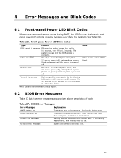
...blink an error message describing the problem (see Table 26). Note: Disabled per default BIOS setup option. Note When no memory was removed, then memory may have been corrupted. If no VGA option ROM is incorrect. The pattern repeats until the system is complete. Replace...The CMOS checksum is found. 4.2 BIOS Error Messages Table 27 lists the error messages and provides a brief description of 16 blinks. Memory Size Decreased Memory size has decreased since the last boot. 4 Error Messages and Blink Codes 4.1 Front-panel Power LED Blink Codes Whenever a recoverable ...
...blink an error message describing the problem (see Table 26). Note: Disabled per default BIOS setup option. Note When no memory was removed, then memory may have been corrupted. If no VGA option ROM is incorrect. The pattern repeats until the system is complete. Replace...The CMOS checksum is found. 4.2 BIOS Error Messages Table 27 lists the error messages and provides a brief description of 16 blinks. Memory Size Decreased Memory size has decreased since the last boot. 4 Error Messages and Blink Codes 4.1 Front-panel Power LED Blink Codes Whenever a recoverable ...
Technical Product Specification
Page 64
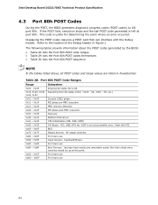
... future use 0xD0 - 0xDF For future use 0xB0 - 0xBF Boot Devices: Includes fixed media and removable media. S2, 0x30 - Table 28. Intel Desktop Board D33217GKE Technical Product Specification 4.3 Port 80h POST Codes During the POST, the BIOS generates diagnostic progress codes (POST codes) to I ...unrecoverable error. S3, etc.) 0x40, 0x50 0x01 - 0x0F Security (SEC) phase 0x11 - 0x1F PEI phase pre MRC execution 0x21 - 0x29 MRC memory detection 0x2A - 0x2F PEI phase post MRC execution 0x31 - 0x35 Recovery 0x36 - 0x3F Platform DXE driver 0x41 - 0x4F CPU Initialization (PEI, DXE,...
... future use 0xD0 - 0xDF For future use 0xB0 - 0xBF Boot Devices: Includes fixed media and removable media. S2, 0x30 - Table 28. Intel Desktop Board D33217GKE Technical Product Specification 4.3 Port 80h POST Codes During the POST, the BIOS generates diagnostic progress codes (POST codes) to I ...unrecoverable error. S3, etc.) 0x40, 0x50 0x01 - 0x0F Security (SEC) phase 0x11 - 0x1F PEI phase pre MRC execution 0x21 - 0x29 MRC memory detection 0x2A - 0x2F PEI phase post MRC execution 0x31 - 0x35 Recovery 0x36 - 0x3F Platform DXE driver 0x41 - 0x4F CPU Initialization (PEI, DXE,...


