

Product Specification
Page 6
Intel Desktop Board D945PVS Technical Product Specification 2 Technical Reference 2.1 Introduction ...37 2.2 Memory Resources ...37 2.2.1 Addressable Memory 37 2.2.2 Memory Map 39 2.3 DMA Channels ...39 2.4 Fixed I/O Map...40 2.5 ... 2.8 Connectors...44 2.8.1 Back Panel Connectors 45 2.8.2 Component-side Connectors 46 2.9 Jumper Block ...55 2.10 Mechanical Considerations 56 2.10.1 Form Factor 56 2.10.2 I/O Shield...57 2.11 Electrical Considerations 58 2.11.1 DC Loading...58 2.11.2 Add-in Board Considerations 58 2.11.3 Fan Connector Current Capability 59 2.11.4 Power Supply Considerations...
Intel Desktop Board D945PVS Technical Product Specification 2 Technical Reference 2.1 Introduction ...37 2.2 Memory Resources ...37 2.2.1 Addressable Memory 37 2.2.2 Memory Map 39 2.3 DMA Channels ...39 2.4 Fixed I/O Map...40 2.5 ... 2.8 Connectors...44 2.8.1 Back Panel Connectors 45 2.8.2 Component-side Connectors 46 2.9 Jumper Block ...55 2.10 Mechanical Considerations 56 2.10.1 Form Factor 56 2.10.2 I/O Shield...57 2.11 Electrical Considerations 58 2.11.1 DC Loading...58 2.11.2 Add-in Board Considerations 58 2.11.3 Fan Connector Current Capability 59 2.11.4 Power Supply Considerations...

Product Specification
Page 7
... Indicator LED 36 14. Board Components ...12 2. Block Diagram...14 3. Memory Channel and DIMM Configuration 17 4. Single Channel (Asymmetric) Mode Configuration with Three DIMMs 20 9. I/O Shield Dimensions 57 23.
... Indicator LED 36 14. Board Components ...12 2. Block Diagram...14 3. Memory Channel and DIMM Configuration 17 4. Single Channel (Asymmetric) Mode Configuration with Three DIMMs 20 9. I/O Shield Dimensions 57 23.
Product Specification
Page 21
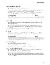
... the chipset Refer to http://developer.intel.com/ Chapter 2 1.5.1 USB The board supports up to eight USB 2.0 ports, supports UHCI and EHCI, and uses UHCI- The ICH7-R provides the USB controller for full-speed devices. Use shielded cable that meets the requirements for all... ports. The Parallel ATA IDE interface supports the following devices: • Intel 82945P Memory Controller Hub (MCH) with Direct Media Interface (DMI) interconnect • Intel 82801GR I /O paths. The ICH7-R is ...
... the chipset Refer to http://developer.intel.com/ Chapter 2 1.5.1 USB The board supports up to eight USB 2.0 ports, supports UHCI and EHCI, and uses UHCI- The ICH7-R provides the USB controller for full-speed devices. Use shielded cable that meets the requirements for all... ports. The Parallel ATA IDE interface supports the following devices: • Intel 82945P Memory Controller Hub (MCH) with Direct Media Interface (DMI) interconnect • Intel 82801GR I /O paths. The ICH7-R is ...

Product Specification
Page 36
... encryption and signature keys at their most vulnerable stages-operations when the keys are being used unencrypted in plain-text form. Intel Desktop Board D945PVS Technical Product Specification 1.12.2.9 WAKE# Signal Wake-up Support When the WAKE# signal on the desktop board that power is...or S5 state. 1.12.2.10 +5 V Standby Power Indicator LED The +5 V standby power indicator LED shows that is specifically designed to shield unencrypted keys and platform authentication information from software-based attacks. For information about TPM Refer to the board. Failure to do so could damage...
... encryption and signature keys at their most vulnerable stages-operations when the keys are being used unencrypted in plain-text form. Intel Desktop Board D945PVS Technical Product Specification 1.12.2.9 WAKE# Signal Wake-up Support When the WAKE# signal on the desktop board that power is...or S5 state. 1.12.2.10 +5 V Standby Power Indicator LED The +5 V standby power indicator LED shows that is specifically designed to shield unencrypted keys and platform authentication information from software-based attacks. For information about TPM Refer to the board. Failure to do so could damage...

Product Specification
Page 57
... indicate the position of each cutout. Technical Reference 2.10.2 I/O Shield The back panel I/O shield for I/O shields relative to pass certification testing. I /O shield. Systems based on this document are given in the ATX specification. NOTE The I /O shields compliant with the ATX chassis specification 2.03 are available from Intel. 1.55 REF [0.061] 22.45 [0.884] 7.01 [0.276] Ø...
... indicate the position of each cutout. Technical Reference 2.10.2 I/O Shield The back panel I/O shield for I/O shields relative to pass certification testing. I /O shield. Systems based on this document are given in the ATX specification. NOTE The I /O shields compliant with the ATX chassis specification 2.03 are available from Intel. 1.55 REF [0.061] 22.45 [0.884] 7.01 [0.276] Ø...

English Product Guide
Page 4
... (1024 bytes) MB Megabyte (1,048,576 bytes) Mbit Megabit (1,048,576 bits) MHz Megahertz (one million hertz) Box Contents • Intel® Desktop Board • I/O shield • One ATA-66/100 cable • Eight locking Serial ATA cables • Two Serial ATA power cables • One floppy ... poster • Integration Guide poster • Printed Product Guide • Game flyer • Configuration and battery caution statement label iv Intel Desktop Board D945PVS Product Guide Terminology The table below gives descriptions to some common terms used in the product guide.
... (1024 bytes) MB Megabyte (1,048,576 bytes) Mbit Megabit (1,048,576 bits) MHz Megahertz (one million hertz) Box Contents • Intel® Desktop Board • I/O shield • One ATA-66/100 cable • Eight locking Serial ATA cables • Two Serial ATA power cables • One floppy ... poster • Integration Guide poster • Printed Product Guide • Game flyer • Configuration and battery caution statement label iv Intel Desktop Board D945PVS Product Guide Terminology The table below gives descriptions to some common terms used in the product guide.

English Product Guide
Page 5
... Desktop Board Features Supported Operating Systems 10 Desktop Board Components 11 Processor...13 Main Memory ...14 Intel® 945P Express Chipset 15 Graphics Subsystem ...15 Audio Subsystem ...15 Input/Output (I/O) Controller ... ...18 Chassis Intrusion...19 Power Management Features 19 ACPI...19 Power Connectors...19 Fan Connectors...19 Fan Speed Control (Intel® Precision Cooling Technology 19 Suspend to RAM (Instantly Available PC Technology 20 Wake from USB...21 Wake from ... 25 Place Battery Marking 25 Use Only for Intended Applications 26 Installing the I/O Shield ...26 v
... Desktop Board Features Supported Operating Systems 10 Desktop Board Components 11 Processor...13 Main Memory ...14 Intel® 945P Express Chipset 15 Graphics Subsystem ...15 Audio Subsystem ...15 Input/Output (I/O) Controller ... ...18 Chassis Intrusion...19 Power Management Features 19 ACPI...19 Power Connectors...19 Fan Connectors...19 Fan Speed Control (Intel® Precision Cooling Technology 19 Suspend to RAM (Instantly Available PC Technology 20 Wake from USB...21 Wake from ... 25 Place Battery Marking 25 Use Only for Intended Applications 26 Installing the I/O Shield ...26 v

English Product Guide
Page 7
... Processor Fan Connector ........31 13. Connecting the IDE Cable 37 19. Internal Headers ...39 21. Location of Other Connectors on Desktop Board D945PVS 46 26. LAN Port LED Locations 16 3. Close the Load Plate ...30 12. Dual Configuration Example 2 32 15. Location of the...Remove the Processor from the Protective Processor Cover/Do Not Touch 29 10. Connecting the Serial ATA Cable 38 20. Installing the I/O Shield 26 5. Desktop Board D945PVS Mounting Screw Hole Locations 27 6. Inserting a PCI Express x16 Card 36 18. Connecting the Rear Panel USB 2.0 and IEEE 1394a ...
... Processor Fan Connector ........31 13. Connecting the IDE Cable 37 19. Internal Headers ...39 21. Location of Other Connectors on Desktop Board D945PVS 46 26. LAN Port LED Locations 16 3. Close the Load Plate ...30 12. Dual Configuration Example 2 32 15. Location of the...Remove the Processor from the Protective Processor Cover/Do Not Touch 29 10. Connecting the Serial ATA Cable 38 20. Installing the I/O Shield 26 5. Desktop Board D945PVS Mounting Screw Hole Locations 27 6. Inserting a PCI Express x16 Card 36 18. Connecting the Rear Panel USB 2.0 and IEEE 1394a ...

English Product Guide
Page 17
Use a shielded cable that fully support USB 2.0 transfer rates. four ports routed to the back panel and four routed to the cable. LED Left Right RJ-45 .../s data rate Hi-Speed USB 2.0 Support NOTE Computer systems that do not support USB 2.0. Desktop Board Features Two LEDs are backward compatible with ICH7R support Intel Matrix Storage Technology (NCQ, Hot Plug, RAID 0, 1, 10, 5, and Matrix RAID). 17 Table 4. USB 1.1 devices will function normally at USB 1.1 speeds. Enhanced IDE Interface The...
Use a shielded cable that fully support USB 2.0 transfer rates. four ports routed to the back panel and four routed to the cable. LED Left Right RJ-45 .../s data rate Hi-Speed USB 2.0 Support NOTE Computer systems that do not support USB 2.0. Desktop Board Features Two LEDs are backward compatible with ICH7R support Intel Matrix Storage Technology (NCQ, Hot Plug, RAID 0, 1, 10, 5, and Matrix RAID). 17 Table 4. USB 1.1 devices will function normally at USB 1.1 speeds. Enhanced IDE Interface The...

English Product Guide
Page 23
... personal injury or equipment damage. NOTE Refer to disconnect power, telecommunications links, networks, or modems before performing any procedures can continue to : • Install the I/O shield • Install and remove the desktop board • Install and remove a processor and memory • Install and remove a PCI Express x16 card • Connect the...
... personal injury or equipment damage. NOTE Refer to disconnect power, telecommunications links, networks, or modems before performing any procedures can continue to : • Install the I/O shield • Install and remove the desktop board • Install and remove a processor and memory • Install and remove a PCI Express x16 card • Connect the...

English Product Guide
Page 24
...short circuit Observe all warnings and cautions in this board. If such a station is not available, you install and test the Intel desktop board, observe all warnings and cautions that instruct you increase safety risk and the possibility of : • Sharp pins... certifications • External I/O cable shielding and filtering • Mounting, grounding, and bonding requirements • Keying connectors when mating the wrong connectors could be careful of noncompliance with the chassis and associated modules. Intel Desktop Board D945PVS Product Guide Follow these guidelines to meet...
...short circuit Observe all warnings and cautions in this board. If such a station is not available, you install and test the Intel desktop board, observe all warnings and cautions that instruct you increase safety risk and the possibility of : • Sharp pins... certifications • External I/O cable shielding and filtering • Mounting, grounding, and bonding requirements • Keying connectors when mating the wrong connectors could be careful of noncompliance with the chassis and associated modules. Intel Desktop Board D945PVS Product Guide Follow these guidelines to meet...

English Product Guide
Page 26
... computers (PC) for installation in the chassis. Press the shield into place so that it fits tightly and securely. Place the shield inside the chassis as shown in the chassis, the shield blocks radio frequency transmissions, protects internal components from the chassis supplier. Intel Desktop Board D945PVS Product Guide Use Only for Intended Applications All...
... computers (PC) for installation in the chassis. Press the shield into place so that it fits tightly and securely. Place the shield inside the chassis as shown in the chassis, the shield blocks radio frequency transmissions, protects internal components from the chassis supplier. Intel Desktop Board D945PVS Product Guide Use Only for Intended Applications All...

English Product Guide
Page 40
...the computer and disconnect the AC power cord. 3. Observe the precautions in "Before You Begin" on the board. Install a correctly keyed and shielded front panel audio cable. Connect the audio cable to the front panel audio header on page 23. 2. Remove the cover. 4. The front ...the cover. 40 Turn off the computer and disconnect the AC power cord. 3. Turn off all peripheral devices connected to the computer. Intel Desktop Board D945PVS Product Guide Installing a Front Panel Audio Solution for the front panel audio header. NOTE: some chassis still use a front panel audio ...
...the computer and disconnect the AC power cord. 3. Observe the precautions in "Before You Begin" on the board. Install a correctly keyed and shielded front panel audio cable. Connect the audio cable to the front panel audio header on page 23. 2. Remove the cover. 4. The front ...the cover. 40 Turn off the computer and disconnect the AC power cord. 3. Turn off all peripheral devices connected to the computer. Intel Desktop Board D945PVS Product Guide Installing a Front Panel Audio Solution for the front panel audio header. NOTE: some chassis still use a front panel audio ...

English Product Guide
Page 43
...): 1. Connect the cables to their respective headers on the desktop board. 5. Remove the front panel USB/IEEE 1394a/audio solution cables. 5. Install a correctly keyed and shielded cable. 6. Replace the cover. 43 Observe the precautions in "Before You Begin" on page 23. 2. OM17735 Figure 22. Observe the precautions in "Before You Begin...
...): 1. Connect the cables to their respective headers on the desktop board. 5. Remove the front panel USB/IEEE 1394a/audio solution cables. 5. Install a correctly keyed and shielded cable. 6. Replace the cover. 43 Observe the precautions in "Before You Begin" on page 23. 2. OM17735 Figure 22. Observe the precautions in "Before You Begin...