
Product Specification
Page 5
...1.1.1 Feature Summary 10 1.1.2 Board Layout 12 1.1.3 Block Diagram 14 1.2 Online Support 15 1.3 Processor 15 1.4 System Memory 16 1.4.1 Memory Configurations 18 1.5 Intel® 945GC Chipset 21 1.5.1 Intel 945GC Graphics Subsystem 21 1.5.2 USB 23 1.5.3 IDE Support 24 1.5.4 Real-Time Clock, CMOS SRAM, and Battery 25 1.6 PCI Express... 32 1.11 Power Management 33 1.11.1 ACPI 33 1.11.2 Hardware Support 35 2 Technical Reference 2.1 Memory Resources 41 2.1.1 Addressable Memory 41 2.1.2 Memory Map 43 2.2 DMA Channels 43 2.3 Fixed I/O Map 44 2.4 PCI Configuration Space Map 45 v
...1.1.1 Feature Summary 10 1.1.2 Board Layout 12 1.1.3 Block Diagram 14 1.2 Online Support 15 1.3 Processor 15 1.4 System Memory 16 1.4.1 Memory Configurations 18 1.5 Intel® 945GC Chipset 21 1.5.1 Intel 945GC Graphics Subsystem 21 1.5.2 USB 23 1.5.3 IDE Support 24 1.5.4 Real-Time Clock, CMOS SRAM, and Battery 25 1.6 PCI Express... 32 1.11 Power Management 33 1.11.1 ACPI 33 1.11.2 Hardware Support 35 2 Technical Reference 2.1 Memory Resources 41 2.1.1 Addressable Memory 41 2.1.2 Memory Map 43 2.2 DMA Channels 43 2.3 Fixed I/O Map 44 2.4 PCI Configuration Space Map 45 v
Product Specification
Page 6
Intel Desktop Board D945GCCR Technical Product Specification 2.5 Interrupts 46 2.6 PCI Conventional Interrupt Routing Map 47 2.7 Connectors and Headers 48 2.7.1 Back Panel Connectors 49 2.7.2 Component-side... 67 3 Overview of BIOS Features 3.1 Introduction 69 3.2 BIOS Flash Memory Organization 70 3.3 Resource Configuration 70 3.3.1 PCI Autoconfiguration 70 3.3.2 PCI IDE Support 71 3.4 System Management BIOS (SMBIOS 71 3.5 BIOS Updates 72 3.5.1 Language Support 72 3.5.2 Custom Splash Screen 72 3.6 Legacy USB Support 73 3.7 Boot Options 73 3.7.1 CD-ROM Boot 73 3.7.2 Network Boot...
Intel Desktop Board D945GCCR Technical Product Specification 2.5 Interrupts 46 2.6 PCI Conventional Interrupt Routing Map 47 2.7 Connectors and Headers 48 2.7.1 Back Panel Connectors 49 2.7.2 Component-side... 67 3 Overview of BIOS Features 3.1 Introduction 69 3.2 BIOS Flash Memory Organization 70 3.3 Resource Configuration 70 3.3.1 PCI Autoconfiguration 70 3.3.2 PCI IDE Support 71 3.4 System Management BIOS (SMBIOS 71 3.5 BIOS Updates 72 3.5.1 Language Support 72 3.5.2 Custom Splash Screen 72 3.6 Legacy USB Support 73 3.7 Boot Options 73 3.7.1 CD-ROM Boot 73 3.7.2 Network Boot...
Product Specification
Page 7
...LAN Connector LED Locations 30 9. Board Dimensions 60 18. I /O Map 44 12. Component-side Connectors and Headers 50 14. Supported Memory Configurations 16 4. I /O Shield Dimensions 61 19. Localized High Temperature Zones 65 Tables 1. Board Components 12 2. Wake-up Devices ...and Events 35 9. Single Channel (Asymmetric) Mode Configuration with Two DIMMs ......... 20 7. Memory Operating Frequencies 17 5. Detailed System Memory Address Map 42 12. Location of Conformity Statement 84 5.1.3 Product Ecology Statements 85 5.1.4 EMC Regulations 89 ...
...LAN Connector LED Locations 30 9. Board Dimensions 60 18. I /O Map 44 12. Component-side Connectors and Headers 50 14. Supported Memory Configurations 16 4. I /O Shield Dimensions 61 19. Localized High Temperature Zones 65 Tables 1. Board Components 12 2. Wake-up Devices ...and Events 35 9. Single Channel (Asymmetric) Mode Configuration with Two DIMMs ......... 20 7. Memory Operating Frequencies 17 5. Detailed System Memory Address Map 42 12. Location of Conformity Statement 84 5.1.3 Product Ecology Statements 85 5.1.4 EMC Regulations 89 ...
Product Specification
Page 9
1 Product Description What This Chapter Contains 1.1 Overview 10 1.2 Online Support 15 1.3 Processor 15 1.4 System Memory 16 1.5 Intel® 945GC Chipset 21 1.6 PCI Express* Connectors 25 1.7 Legacy I/O Controller 26 1.8 Audio Subsystem 27 1.9 LAN Subsystem 29 1.10 Hardware Management Subsystem 31 1.11 Power Management 33 9
1 Product Description What This Chapter Contains 1.1 Overview 10 1.2 Online Support 15 1.3 Processor 15 1.4 System Memory 16 1.5 Intel® 945GC Chipset 21 1.6 PCI Express* Connectors 25 1.7 Legacy I/O Controller 26 1.8 Audio Subsystem 27 1.9 LAN Subsystem 29 1.10 Hardware Management Subsystem 31 1.11 Power Management 33 9
Product Specification
Page 10
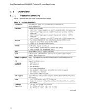
Intel Desktop Board D945GCCR Technical Product Specification 1.1 Overview 1.1.1 Feature Summary Table 1 summarizes the major features of : • Intel® 82945GC Graphics Memory Controller Hub (GMCH) • Intel® 82801GB I/O Controller Hub (ICH7) Intel® GMA950 onboard graphics subsystem 6-channel (5.1) audio subsystem with three .../100 Mbits/sec LAN subsystem using the Intel® 82562G Platform LAN Connect (PLC) device • Intel® BIOS (resident in the SPI Flash device) • Support for up to 4 GB of system memory Intel® 945GC Chipset, consisting of the...
Intel Desktop Board D945GCCR Technical Product Specification 1.1 Overview 1.1.1 Feature Summary Table 1 summarizes the major features of : • Intel® 82945GC Graphics Memory Controller Hub (GMCH) • Intel® 82801GB I/O Controller Hub (ICH7) Intel® GMA950 onboard graphics subsystem 6-channel (5.1) audio subsystem with three .../100 Mbits/sec LAN subsystem using the Intel® 82562G Platform LAN Connect (PLC) device • Intel® BIOS (resident in the SPI Flash device) • Support for up to 4 GB of system memory Intel® 945GC Chipset, consisting of the...
Product Specification
Page 16
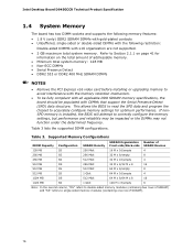
... read the SPD data and program the chipset to correctly configure the memory settings, but performance and reliability may not function under the determined frequency. Intel Desktop Board D945GCCR Technical Product Specification 1.4 System Memory The board has two DIMM sockets and supports the following memory features: • 1.8 V (only) DDR2 SDRAM DIMMs with gold-plated contacts •...
... read the SPD data and program the chipset to correctly configure the memory settings, but performance and reliability may not function under the determined frequency. Intel Desktop Board D945GCCR Technical Product Specification 1.4 System Memory The board has two DIMM sockets and supports the following memory features: • 1.8 V (only) DDR2 SDRAM DIMMs with gold-plated contacts •...
Product Specification
Page 18
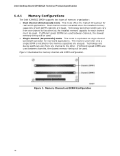
... channel mode is installed or the memory capacities are equal. This mode is equivalent to the other . Figure 3. Technology and device width can vary from one channel to single channel bandwidth operation for real world applications. Intel Desktop Board D945GCCR Technical Product Specification 1.4.1 Memory Configurations The Intel 82945GC GMCH supports two types of both DIMM channels...
... channel mode is installed or the memory capacities are equal. This mode is equivalent to the other . Figure 3. Technology and device width can vary from one channel to single channel bandwidth operation for real world applications. Intel Desktop Board D945GCCR Technical Product Specification 1.4.1 Memory Configurations The Intel 82945GC GMCH supports two types of both DIMM channels...

Product Specification
Page 21
...; Anti-aliased lines 21 The component also provides integrated graphics capabilities supporting 3D, 2D and display capabilities. The ICH7 is disabled. 1.5.1.1 Intel® GMA950 Graphics Controller The Intel GMA950 graphics controller features the following: • 400 MHz core ...⎯ Maximum 3D supported resolution of the following devices: • Intel 82945GC Graphics Memory Controller Hub (GMCH) with DMI interconnect The GMCH component provides interfaces to http://developer.intel.com/ Chapter 2 1.5.1 Intel 945GC Graphics Subsystem The Intel 945GC chipset contains two...
...; Anti-aliased lines 21 The component also provides integrated graphics capabilities supporting 3D, 2D and display capabilities. The ICH7 is disabled. 1.5.1.1 Intel® GMA950 Graphics Controller The Intel GMA950 graphics controller features the following: • 400 MHz core ...⎯ Maximum 3D supported resolution of the following devices: • Intel 82945GC Graphics Memory Controller Hub (GMCH) with DMI interconnect The GMCH component provides interfaces to http://developer.intel.com/ Chapter 2 1.5.1 Intel 945GC Graphics Subsystem The Intel 945GC chipset contains two...

Product Specification
Page 22
... Advanced Digital Display 2 or 2+ (ADD2/ADD2+) cards, support for TV-out/TV-in the BIOS Setup program) for compatibility with 200 MHz pixel clocks using VGA graphics under DOS. DVMT ensures the most efficient use of available system memory for maximum 2-D/3-D graphics performance. Intel Desktop Board D945GCCR Technical Product Specification • Video ⎯ Hardware...
... Advanced Digital Display 2 or 2+ (ADD2/ADD2+) cards, support for TV-out/TV-in the BIOS Setup program) for compatibility with 200 MHz pixel clocks using VGA graphics under DOS. DVMT ensures the most efficient use of available system memory for maximum 2-D/3-D graphics performance. Intel Desktop Board D945GCCR Technical Product Specification • Video ⎯ Hardware...

Product Specification
Page 25
...PCI Conventional compliant operating systems. Additional features of the PCI Express interface include the following PCI Express connectors: • One PCI Express x16 connector supporting simultaneous transfer speeds up to Figure 13, page 50 1.5.4 Real-Time Clock, CMOS SRAM, and Battery A coin-cell battery (CR2032) powers ...the real-time clock and CMOS memory. NOTE If the battery and AC power fail, custom defaults, if previously saved, will be loaded into a wall socket, the battery has an...
...PCI Conventional compliant operating systems. Additional features of the PCI Express interface include the following PCI Express connectors: • One PCI Express x16 connector supporting simultaneous transfer speeds up to Figure 13, page 50 1.5.4 Real-Time Clock, CMOS SRAM, and Battery A coin-cell battery (CR2032) powers ...the real-time clock and CMOS memory. NOTE If the battery and AC power fail, custom defaults, if previously saved, will be loaded into a wall socket, the battery has an...

Product Specification
Page 69
...be used to put the Desktop Board in the Serial Peripheral Interface Flash Memory (SPI Flash) and can be updated using a disk-based program. ... POST, the PCI auto-configuration utility, and Plug and Play support. The menu bar is in the BIOS and reports if the... pressing the key after the Power-On Self-Test (POST) memory test begins and before the operating system boot begins. The BIOS...3.1 Introduction 69 3.2 BIOS Flash Memory Organization 70 3.3 Resource Configuration 70 3.4 System Management BIOS (SMBIOS 71 3.5 BIOS Updates 72 3.6 Legacy USB Support 73 3.7 Boot Options 73 3.8...
...be used to put the Desktop Board in the Serial Peripheral Interface Flash Memory (SPI Flash) and can be updated using a disk-based program. ... POST, the PCI auto-configuration utility, and Plug and Play support. The menu bar is in the BIOS and reports if the... pressing the key after the Power-On Self-Test (POST) memory test begins and before the operating system boot begins. The BIOS...3.1 Introduction 69 3.2 BIOS Flash Memory Organization 70 3.3 Resource Configuration 70 3.4 System Management BIOS (SMBIOS 71 3.5 BIOS Updates 72 3.6 Legacy USB Support 73 3.7 Boot Options 73 3.8...
Product Specification
Page 71
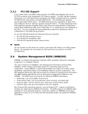
...system can obtain the SMBIOS information. 71 The main component of SMBIOS is a Desktop Management Interface (DMI) compliant method for accessing this support, an SMBIOS service-level application running on the capability of the drive. The MIF database defines the data and provides the method for ... such as the BIOS revision level • Fixed-system data, such as peripherals, serial numbers, and asset tags • Resource data, such as memory size, cache size, and processor speed • Dynamic data, such as event detection and error logging Non-Plug and Play operating systems, such as...
...system can obtain the SMBIOS information. 71 The main component of SMBIOS is a Desktop Management Interface (DMI) compliant method for accessing this support, an SMBIOS service-level application running on the capability of the drive. The MIF database defines the data and provides the method for ... such as the BIOS revision level • Fixed-system data, such as peripherals, serial numbers, and asset tags • Resource data, such as memory size, cache size, and processor speed • Dynamic data, such as event detection and error logging Non-Plug and Play operating systems, such as...

Product Specification
Page 72
...15 3.5.1 Language Support The BIOS Setup program and help messages are supported in US English. Check the Intel website for details. 3.5.2 Custom Splash Screen During POST, an Intel® splash screen is available from a file on the Web. • Intel® Flash Memory Update Utility, which...screen can be augmented with the Intel branded logo. Intel Desktop Board D945GCCR Technical Product Specification 3.5 BIOS Updates The BIOS can be updated using either of the following utilities, which are available on the Intel World Wide Web site: • Intel® Express BIOS Update utility...
...15 3.5.1 Language Support The BIOS Setup program and help messages are supported in US English. Check the Intel website for details. 3.5.2 Custom Splash Screen During POST, an Intel® splash screen is available from a file on the Web. • Intel® Flash Memory Update Utility, which...screen can be augmented with the Intel branded logo. Intel Desktop Board D945GCCR Technical Product Specification 3.5 BIOS Updates The BIOS can be updated using either of the following utilities, which are available on the Intel World Wide Web site: • Intel® Express BIOS Update utility...
Intel Desktop Board D945GCCR Specification Update PFD
Page 6
... have to do anything to achieve proper device functionality as a result of the document. Intel intends to 4 GB of system memory support and replace with 2 GB of the Technical Specification will be updated in a future revision of system memory 6 Intel Desktop Board D945GCCR Specification Update Plan Fix: This erratum may be fixed in a future revision of...
... have to do anything to achieve proper device functionality as a result of the document. Intel intends to 4 GB of system memory support and replace with 2 GB of the Technical Specification will be updated in a future revision of system memory 6 Intel Desktop Board D945GCCR Specification Update Plan Fix: This erratum may be fixed in a future revision of...
Intel Desktop Board D945GCCR Product Guide English
Page 5
...Desktop Board Components 11 Processor ...13 Main Memory...13 Intel® 945GC Express Chipset 15 Onboard Audio Subsystem 15 Input/Output (I/O) Controller 16 LAN Subsystem 16 LAN Subsystem Software 16 RJ-45 LAN Connector LEDs 17 Hi-Speed USB 2.0 Support 17 Enhanced IDE Interface 18 Serial ATA...18...+5 V Standby Power Indicator LED 22 Wake from USB 23 Wake from PS/2 Keyboard/Mouse 23 PME# Signal Wake-up Support 23 WAKE# Signal Wake-up Support 23 Speaker...23 Battery ...23 Real-Time Clock 23 2 Installing and Replacing Desktop Board Components Before You Begin 25 Installation ...
...Desktop Board Components 11 Processor ...13 Main Memory...13 Intel® 945GC Express Chipset 15 Onboard Audio Subsystem 15 Input/Output (I/O) Controller 16 LAN Subsystem 16 LAN Subsystem Software 16 RJ-45 LAN Connector LEDs 17 Hi-Speed USB 2.0 Support 17 Enhanced IDE Interface 18 Serial ATA...18...+5 V Standby Power Indicator LED 22 Wake from USB 23 Wake from PS/2 Keyboard/Mouse 23 PME# Signal Wake-up Support 23 WAKE# Signal Wake-up Support 23 Speaker...23 Battery ...23 Real-Time Clock 23 2 Installing and Replacing Desktop Board Components Before You Begin 25 Installation ...
Intel Desktop Board D945GCCR Product Guide English
Page 9
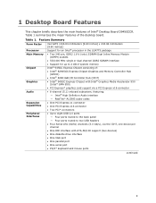
... features of the desktop board. Table 1 summarizes the major features of Intel® Desktop Board D945GCCR. Feature Summary Form Factor Processor Main Memory Chipset Graphics Audio Expansion Capabilities Peripheral Interfaces microATX (243.84 millimeters [9.60 inches] x 243.84 millimeters [9.60 inches]) Support for an Intel® processor in the LGA775 package • Two 240-pin...
... features of the desktop board. Table 1 summarizes the major features of Intel® Desktop Board D945GCCR. Feature Summary Form Factor Processor Main Memory Chipset Graphics Audio Expansion Capabilities Peripheral Interfaces microATX (243.84 millimeters [9.60 inches] x 243.84 millimeters [9.60 inches]) Support for an Intel® processor in the LGA775 package • Two 240-pin...

Intel Desktop Board D945GCCR Product Guide English
Page 13
.... The BIOS will see a notification to 2.0 GB utilizing 512 Mb and 1 Gb technology Intel recommends using memory from the tested memory lists, available at power up. The supported processors list for Desktop Board D945GCCR is located on the web at: http://www.intel.com/go/FindCPU Related Links: Go to the following links or pages for...
.... The BIOS will see a notification to 2.0 GB utilizing 512 Mb and 1 Gb technology Intel recommends using memory from the tested memory lists, available at power up. The supported processors list for Desktop Board D945GCCR is located on the web at: http://www.intel.com/go/FindCPU Related Links: Go to the following links or pages for...

Intel Desktop Board D945GCCR Product Guide English
Page 15
...information about the Intel 945GC Express Chipset: http://www.intel.com/products/desktop/chipsets/index.htm?iid=chips_body+desk Onboard Audio Subsystem Desktop Board D945GCCR has a flexible... including functionality for more information about: • Audio drivers and utilities http://support.intel.com/support/motherboards/desktop/ • Installing the front panel audio solution, page 44 ... the following devices: • Intel 82945GC Express Chipset Graphics and Memory Controller Hub (GMCH) • Intel 82801GB I/O Controller Hub (ICH7) The Intel 945GC Express Chipset contains two separate...
...information about the Intel 945GC Express Chipset: http://www.intel.com/products/desktop/chipsets/index.htm?iid=chips_body+desk Onboard Audio Subsystem Desktop Board D945GCCR has a flexible... including functionality for more information about: • Audio drivers and utilities http://support.intel.com/support/motherboards/desktop/ • Installing the front panel audio solution, page 44 ... the following devices: • Intel 82945GC Express Chipset Graphics and Memory Controller Hub (GMCH) • Intel 82801GB I/O Controller Hub (ICH7) The Intel 945GC Express Chipset contains two separate...
Intel Desktop Board D945GCCR Product Guide English
Page 21
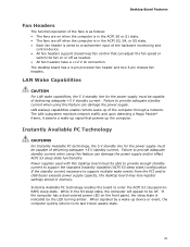
...fan header and two 3-pin chassis fan headers. Failure to a tachometer input of the hardware monitoring and control device. • All fan headers support closed-loop fan control that powers up of the computer through a network. Failure to its last known awake state. 21 When signaled by the LED... Features Fan Headers The function/operation of the fans is as needed. • All fan headers have a +12 V dc connection. While in memory. The LAN subsystem monitors network traffic and upon detecting a Magic Packet* frame, it asserts a wake-up signal that can adjust the fan speed or...
...fan header and two 3-pin chassis fan headers. Failure to a tachometer input of the hardware monitoring and control device. • All fan headers support closed-loop fan control that powers up of the computer through a network. Failure to its last known awake state. 21 When signaled by the LED... Features Fan Headers The function/operation of the fans is as needed. • All fan headers have a +12 V dc connection. While in memory. The LAN subsystem monitors network traffic and upon detecting a Magic Packet* frame, it asserts a wake-up signal that can adjust the fan speed or...

Intel Desktop Board D945GCCR Product Guide English
Page 22
...support.intel.com/support/motherboards/desktop/ 22 Figure 3. Add-in cards that support this LED is lit, standby power is standby power still present on standby current requirements for the desktop board, refer to the Technical Product Specification by going to the board. Intel Desktop Board D945GCCR ...Product Guide The desktop board supports the PCI Bus Power Management Interface Specification. For example, when this specification can participate in Figure 3, is lit when there is still present at the memory module sockets and the PCI bus connectors. The desktop board...
...support.intel.com/support/motherboards/desktop/ 22 Figure 3. Add-in cards that support this LED is lit, standby power is standby power still present on standby current requirements for the desktop board, refer to the Technical Product Specification by going to the board. Intel Desktop Board D945GCCR ...Product Guide The desktop board supports the PCI Bus Power Management Interface Specification. For example, when this specification can participate in Figure 3, is lit when there is still present at the memory module sockets and the PCI bus connectors. The desktop board...


