
Product Guide
Page 5
...Support 19 Battery ...22 Real-Time Clock 22 2 Installing and Replacing Desktop Board Components Before You Begin 23 Installation Precautions 25 Prevent Power Supply Overload 25 Observe Safety and Regulatory Requirements 25 Installing the I/O Shield 26 Installing and Removing the Desktop Board 27 Installing and Removing ...Memory 28 Connecting SATA Drives 29 Installing a Wireless LAN Card in the PCI Express Mini Card Slot 30 Installing an Intel® Z-U130 USB Solid-State Drive or Compatible Device 32 Connecting to the Internal Headers 33 Connecting to the Front Panel ...
...Support 19 Battery ...22 Real-Time Clock 22 2 Installing and Replacing Desktop Board Components Before You Begin 23 Installation Precautions 25 Prevent Power Supply Overload 25 Observe Safety and Regulatory Requirements 25 Installing the I/O Shield 26 Installing and Removing the Desktop Board 27 Installing and Removing ...Memory 28 Connecting SATA Drives 29 Installing a Wireless LAN Card in the PCI Express Mini Card Slot 30 Installing an Intel® Z-U130 USB Solid-State Drive or Compatible Device 32 Connecting to the Internal Headers 33 Connecting to the Front Panel ...

Product Guide
Page 7
... 4. S/PDIF Header 34 8. Front Panel USB Header 35 10. POST Error Messages 52 18. Regulatory Compliance Marks 62 21. Contents Figures 1. Intel Desktop Board D525MW Mounting Screw Holes 27 7. Connecting Power Supply Cables 38 15. Serial Port Header (COM 1 35 9. Front Panel Wireless Activity LED Header 36 13. Jumper Settings for BIOS Recovery 49...
... 4. S/PDIF Header 34 8. Front Panel USB Header 35 10. POST Error Messages 52 18. Regulatory Compliance Marks 62 21. Contents Figures 1. Intel Desktop Board D525MW Mounting Screw Holes 27 7. Connecting Power Supply Cables 38 15. Serial Port Header (COM 1 35 9. Front Panel Wireless Activity LED Header 36 13. Jumper Settings for BIOS Recovery 49...

Product Guide
Page 23
...the Desktop Board • Install and remove system memory • Connect SATA drives • Install a Wireless LAN card • Install an Intel Z-U130 USB Solid-State Drive or compatible device • Connect to record information about your computer, such as model, serial numbers, installed options...follow the steps in each procedure in the correct order. • Set up a log to internal headers • Connect chassis fan and power supply cables • Set the BIOS configuration jumper • Clear passwords • Replace the battery Before You Begin CAUTION The procedures in this...
...the Desktop Board • Install and remove system memory • Connect SATA drives • Install a Wireless LAN card • Install an Intel Z-U130 USB Solid-State Drive or compatible device • Connect to record information about your computer, such as model, serial numbers, installed options...follow the steps in each procedure in the correct order. • Set up a log to internal headers • Connect chassis fan and power supply cables • Set the BIOS configuration jumper • Clear passwords • Replace the battery Before You Begin CAUTION The procedures in this...

Product Guide
Page 25
... personnel. Prevent Power Supply Overload Do not overload the power supply output. Observe Safety and Regulatory Requirements Read and adhere to the instructions in the installation instructions. To avoid overloading the power supply, make sure that instruct you install and test the Intel Desktop Board, ...observe all the modules within the computer is less than the output current rating of the power supply. Refer to wires that could cause ...
... personnel. Prevent Power Supply Overload Do not overload the power supply output. Observe Safety and Regulatory Requirements Read and adhere to the instructions in the installation instructions. To avoid overloading the power supply, make sure that instruct you install and test the Intel Desktop Board, ...observe all the modules within the computer is less than the output current rating of the power supply. Refer to wires that could cause ...

Product Guide
Page 38
Connecting Power Supply Cables 1. Figure 14 shows the location of the power connectors. Connect the 12 V processor core voltage power supply cable to the 2 x 12 pin connector (Figure 14, B). 3. Observe the precautions in damage to the board or the system may not function properly. Connect the main power supply cable to the 2 x 2 pin connector (Figure 14, A). 38 Intel Desktop Board D525MW Product Guide Connecting a Power Supply CAUTION Failure to connect an appropriate power supply to the Desktop Board may result in "Before You Begin" on page 23. 2. Figure 14.
Connecting Power Supply Cables 1. Figure 14 shows the location of the power connectors. Connect the 12 V processor core voltage power supply cable to the 2 x 12 pin connector (Figure 14, B). 3. Observe the precautions in damage to the board or the system may not function properly. Connect the main power supply cable to the 2 x 2 pin connector (Figure 14, A). 38 Intel Desktop Board D525MW Product Guide Connecting a Power Supply CAUTION Failure to connect an appropriate power supply to the Desktop Board may result in "Before You Begin" on page 23. 2. Figure 14.

Product Guide
Page 41
... du possible. VIKTIGT! Installing and Replacing Desktop Board Components 12. When the voltage drops below . 13. Batteries should be in , the standby current from the power supply extends the life of explosion if the battery is not plugged into a wall socket, the battery has an estimated life of the battery. FORHOLDSREGEL Eksplosionsfare...
... du possible. VIKTIGT! Installing and Replacing Desktop Board Components 12. When the voltage drops below . 13. Batteries should be in , the standby current from the power supply extends the life of explosion if the battery is not plugged into a wall socket, the battery has an estimated life of the battery. FORHOLDSREGEL Eksplosionsfare...

Product Guide
Page 61
Ensure Electromagnetic Compatibility (EMC) Compliance Before computer integration, make sure that the power supply and other modules or peripherals, as applicable, have passed Class B EMC testing and are not Class B EMC compliant before integration, ... to the following when reading the installation instructions for home use, and has acquired electromagnetic conformity registration, so it can be hazardous If the power supply and other modules or peripherals, as applicable, are marked accordingly. Regulatory Compliance Korea Class B Statement Korea Class B Statement translation: This equipment...
Ensure Electromagnetic Compatibility (EMC) Compliance Before computer integration, make sure that the power supply and other modules or peripherals, as applicable, have passed Class B EMC testing and are not Class B EMC compliant before integration, ... to the following when reading the installation instructions for home use, and has acquired electromagnetic conformity registration, so it can be hazardous If the power supply and other modules or peripherals, as applicable, are marked accordingly. Regulatory Compliance Korea Class B Statement Korea Class B Statement translation: This equipment...

Product Guide
Page 63
...: In Europe The CE mark indicates compliance with safety requirements. In the United States A certification mark by a Nationally Recognized Testing Laboratory (NRTL) such as the power supply, peripheral drives, wiring, and cables; If the chassis and other directives, such as CSA or cUL signifies compliance with all applicable European requirements. Regulatory Compliance...
...: In Europe The CE mark indicates compliance with safety requirements. In the United States A certification mark by a Nationally Recognized Testing Laboratory (NRTL) such as the power supply, peripheral drives, wiring, and cables; If the chassis and other directives, such as CSA or cUL signifies compliance with all applicable European requirements. Regulatory Compliance...

Product Specification
Page 10
Feature Summary (continued) BIOS • Intel® BIOS (resident in the SPI Flash device) • Support for Advanced Configuration and Power Interface (ACPI), Plug and Play, and SMBIOS Instantly Available PC Technology Expansion Capabilities Hardware Monitor Subsystem • Support ... to detect out of range power supply voltages • Thermal sense to detect out of range thermal values • One fan header • One fan sense input used to monitor fan activity • Fan speed control 10 Intel Desktop Board D525MW and Intel Desktop Board D525MWV Technical Product Specification...
Feature Summary (continued) BIOS • Intel® BIOS (resident in the SPI Flash device) • Support for Advanced Configuration and Power Interface (ACPI), Plug and Play, and SMBIOS Instantly Available PC Technology Expansion Capabilities Hardware Monitor Subsystem • Support ... to detect out of range power supply voltages • Thermal sense to detect out of range thermal values • One fan header • One fan sense input used to monitor fan activity • Fan speed control 10 Intel Desktop Board D525MW and Intel Desktop Board D525MWV Technical Product Specification...

Product Specification
Page 14
...heat dissipation effectiveness. Chassis venting locations are recommended above the processor heatsink area for the Intel Desktop Board D525MW and Intel Desktop Board D525MWV Supported processors Chipset information BIOS and driver updates Tested memory Integration information Visit...Core Intel Atom processor with integrated graphics and integrated memory controller. NOTE The board is designed to Section 2.2.2.3, page 45 14 Intel Desktop Board D525MW and Intel Desktop Board D525MWV Technical Product Specification 1.2 Online Support To find information about Power supply connectors...
...heat dissipation effectiveness. Chassis venting locations are recommended above the processor heatsink area for the Intel Desktop Board D525MW and Intel Desktop Board D525MWV Supported processors Chipset information BIOS and driver updates Tested memory Integration information Visit...Core Intel Atom processor with integrated graphics and integrated memory controller. NOTE The board is designed to Section 2.2.2.3, page 45 14 Intel Desktop Board D525MW and Intel Desktop Board D525MWV Technical Product Specification 1.2 Online Support To find information about Power supply connectors...

Product Specification
Page 20
... be accurate. When the voltage drops below a certain level, the BIOS Setup program settings stored in , the standby current from the power supply extends the life of the battery. 1.7 Legacy I/O Controller One serial port header One serial port connector on page 11 shows the location... header The serial port header signal mapping Refer to ± 13 minutes/year at power-on page 41 20 For information about The location of three years. Intel Desktop Board D525MW and Intel Desktop Board D525MWV Technical Product Specification 1.6 Real-Time Clock Subsystem A coin-cell battery ...
... be accurate. When the voltage drops below a certain level, the BIOS Setup program settings stored in , the standby current from the power supply extends the life of the battery. 1.7 Legacy I/O Controller One serial port header One serial port connector on page 11 shows the location... header The serial port header signal mapping Refer to ± 13 minutes/year at power-on page 41 20 For information about The location of three years. Intel Desktop Board D525MW and Intel Desktop Board D525MWV Technical Product Specification 1.6 Real-Time Clock Subsystem A coin-cell battery ...

Product Specification
Page 28
... knowledge of the various system and power states. Intel Desktop Board D525MW and Intel Desktop Board D525MWV Technical Product Specification 1.11.1.1 System States and Power States Under ACPI, the operating system directs all system and device power state transitions. Devices that are being...or external source. Power States and Targeted System Power Global States G0 - S5 - No power No power to the system. Table 7 lists the power states supported by the system's power supply. device specification specific. Context not saved. AC power is required. no power except for a ...
... knowledge of the various system and power states. Intel Desktop Board D525MW and Intel Desktop Board D525MWV Technical Product Specification 1.11.1.1 System States and Power States Under ACPI, the operating system directs all system and device power state transitions. Devices that are being...or external source. Power States and Targeted System Power Global States G0 - S5 - No power No power to the system. Table 7 lists the power states supported by the system's power supply. device specification specific. Context not saved. AC power is required. no power except for a ...

Product Specification
Page 45
...and dual-slot riser cards for the PCI Conventional bus connector: • • 2.2.2.3 Power Supply Connector The board has a 2 x 12 power connector (see Table 23). Power Connector Pin 1 2 3 4 5 6 7 8 9 10 11 12 Signal Name +3.3 V +3.3 V Ground +5 V Ground +5 V Ground PWRGD (Power Good) +5 V (Standby) +12 V +12 V No connect Pin 13 14 15... 16 17 18 19 20 21 22 23 24 Signal Name +3.3 V -12 V Ground PS-ON# (power supply remote on the board. SMBus signals are as follows: ⎯ The SMBus clock line is connected to pin A40. ⎯ The SMBus data line is...
...and dual-slot riser cards for the PCI Conventional bus connector: • • 2.2.2.3 Power Supply Connector The board has a 2 x 12 power connector (see Table 23). Power Connector Pin 1 2 3 4 5 6 7 8 9 10 11 12 Signal Name +3.3 V +3.3 V Ground +5 V Ground +5 V Ground PWRGD (Power Good) +5 V (Standby) +12 V +12 V No connect Pin 13 14 15... 16 17 18 19 20 21 22 23 24 Signal Name +3.3 V -12 V Ground PS-ON# (power supply remote on the board. SMBus signals are as follows: ⎯ The SMBus clock line is connected to pin A40. ⎯ The SMBus data line is...

Product Specification
Page 47
... 6 and 8 can be connected to a single- Table 25. The switch must pull the SW_ON# pin to ground for at least 50 ms to signal the power supply circuitry to switch on or off. (The time requirement is due to internal debounce circuitry on the board.) At least two seconds must pass before... the power supply circuitry will recognize another on/off /hibernate (S5/S4) Sleeping (S3) Running/Away (S0/S1) NOTE The LED states listed in Table 25 are default...
... 6 and 8 can be connected to a single- Table 25. The switch must pull the SW_ON# pin to ground for at least 50 ms to signal the power supply circuitry to switch on or off. (The time requirement is due to internal debounce circuitry on the board.) At least two seconds must pass before... the power supply circuitry will recognize another on/off /hibernate (S5/S4) Sleeping (S3) Running/Away (S0/S1) NOTE The LED states listed in Table 25 are default...

Product Specification
Page 54
...surrounding the chassis. TDP TA external 54 Intel Desktop Board D525MW and Intel Desktop Board D525MWV Technical Product Specification Table 28. This information should be specified for passive heatsink design in conjunction with either a power supply fan or a built-in this section can... vent. The external ambient temperature should be measured just upstream of a passive heatsink. Junction-to dissipate the thermal design power. TA)/TDP. Passive heatsink describes a thermal solution without a fan attached. TIM Thermal Interface Material: the thermally conductive ...
...surrounding the chassis. TDP TA external 54 Intel Desktop Board D525MW and Intel Desktop Board D525MWV Technical Product Specification Table 28. This information should be specified for passive heatsink design in conjunction with either a power supply fan or a built-in this section can... vent. The external ambient temperature should be measured just upstream of a passive heatsink. Junction-to dissipate the thermal design power. TA)/TDP. Passive heatsink describes a thermal solution without a fan attached. TIM Thermal Interface Material: the thermally conductive ...
Product Specification
Page 57
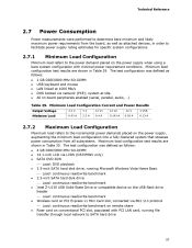
... SATA DVD-R/W ⎯ Load: DVD playback 3.5-inch SATA hard disk drive, running file transfer through local network to the power demand placed on the power supply when using a bare system configuration with PCI LAN card, running Microsoft Windows Vista Home Basic ⎯ Load: continuous read/...write benchmark 2.5-inch SATA hard disk drive ⎯ Load: continuous read/write benchmark Intel Z-U130 USB Solid-State Drive or compatible...
... SATA DVD-R/W ⎯ Load: DVD playback 3.5-inch SATA hard disk drive, running file transfer through local network to the power demand placed on the power supply when using a bare system configuration with PCI LAN card, running Microsoft Windows Vista Home Basic ⎯ Load: continuous read/...write benchmark 2.5-inch SATA hard disk drive ⎯ Load: continuous read/write benchmark Intel Z-U130 USB Solid-State Drive or compatible...


