
Product Guide
Page 5
Contents 1 Desktop Board Features Desktop Board Components 11 Processor ...13 System Memory 13 Integrated Graphics Subsystem 14 Intel® NM10 Express Chipset 14 Operating System Support 14 Onboard Audio Subsystem 14 Legacy Input/Output (I/O) Controller 16 LAN Subsystem 16 USB ...Installing the I/O Shield 26 Installing and Removing the Desktop Board 27 Installing and Removing Memory 28 Connecting SATA Drives 29 Installing a Wireless LAN Card in the PCI Express Mini Card Slot 30 Installing an Intel® Z-U130 USB Solid-State Drive or Compatible Device 32 Connecting to the ...
Contents 1 Desktop Board Features Desktop Board Components 11 Processor ...13 System Memory 13 Integrated Graphics Subsystem 14 Intel® NM10 Express Chipset 14 Operating System Support 14 Onboard Audio Subsystem 14 Legacy Input/Output (I/O) Controller 16 LAN Subsystem 16 USB ...Installing the I/O Shield 26 Installing and Removing the Desktop Board 27 Installing and Removing Memory 28 Connecting SATA Drives 29 Installing a Wireless LAN Card in the PCI Express Mini Card Slot 30 Installing an Intel® Z-U130 USB Solid-State Drive or Compatible Device 32 Connecting to the ...

Product Guide
Page 6
Intel Desktop Board D525MW Product Guide 3 Updating the BIOS Updating the BIOS with the Intel® Express BIOS Update Utility 47 Updating the BIOS with the Iflash Memory Update Utility 48 Obtaining the BIOS Update File 48 Using the Iflash Memory Update Utility 48 Recovering the BIOS 49 A Board Status and Error Messages BIOS Beep Codes...
Intel Desktop Board D525MW Product Guide 3 Updating the BIOS Updating the BIOS with the Intel® Express BIOS Update Utility 47 Updating the BIOS with the Iflash Memory Update Utility 48 Obtaining the BIOS Update File 48 Using the Iflash Memory Update Utility 48 Recovering the BIOS 49 A Board Status and Error Messages BIOS Beep Codes...

Product Guide
Page 7
...Front Panel USB Header 35 10. Front Panel Header Signal Names 36 12. AcceptableDrives/Media Types for Intel HD Audio 34 6. Installing System Memory 28 8. Intel Desktop Board D525MW China RoHS Material Self Declaration Table 58 Tables 1. Feature Summary 9 2. Front Panel Audio Header for ...Front Panel Wireless Activity LED Header 36 13. Installing the I/O Shield 26 6. BIOS Configuration Jumper Block 39 16. Intel Desktop Board D525MW Components 12 3. LAN Status LEDs 17 5. BIOS Front-panel Power LED Blink Codes 52 17. Regulatory Compliance Marks 62 21...
...Front Panel USB Header 35 10. Front Panel Header Signal Names 36 12. AcceptableDrives/Media Types for Intel HD Audio 34 6. Installing System Memory 28 8. Intel Desktop Board D525MW China RoHS Material Self Declaration Table 58 Tables 1. Feature Summary 9 2. Front Panel Audio Header for ...Front Panel Wireless Activity LED Header 36 13. Installing the I/O Shield 26 6. BIOS Configuration Jumper Block 39 16. Intel Desktop Board D525MW Components 12 3. LAN Status LEDs 17 5. BIOS Front-panel Power LED Blink Codes 52 17. Regulatory Compliance Marks 62 21...
Product Guide
Page 9
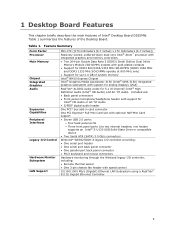
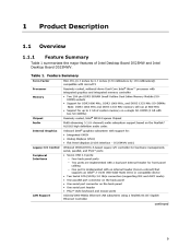
... operate at 800 MHz only) • Support for up to 4 GB of system memory Intel® NM10 Express Chipset Intel® Graphics Media Accelerator 3150 (Intel® GMA 3150) integrated graphics subsystem with support for analog displays (VGA) RealTek* ...) Ethernet LAN Subsystem using a RealTek* 8111E Gigabit Ethernet Controller 9 Table 1 summarizes the features of Intel® Desktop Board D525MW. Feature Summary Form Factor Processor Main Memory Chipset Integrated Graphics Audio Expansion Capabilities Peripheral Interfaces Legacy I /O controller, including: • Remote thermal sensor...
... operate at 800 MHz only) • Support for up to 4 GB of system memory Intel® NM10 Express Chipset Intel® Graphics Media Accelerator 3150 (Intel® GMA 3150) integrated graphics subsystem with support for analog displays (VGA) RealTek* ...) Ethernet LAN Subsystem using a RealTek* 8111E Gigabit Ethernet Controller 9 Table 1 summarizes the features of Intel® Desktop Board D525MW. Feature Summary Form Factor Processor Main Memory Chipset Integrated Graphics Audio Expansion Capabilities Peripheral Interfaces Legacy I /O controller, including: • Remote thermal sensor...

Product Guide
Page 13
... MHz SO-DIMMs operate at power up. System Memory NOTE To be fully compliant with all applicable Intel® SDRAM memory specifications, the board should be passively cooled in a properly ventilated chassis. If your memory modules do not support SPD, you will attempt ...only) • Serial Presence Detect (SPD) memory only • Non-ECC memory • Up to configure the memory controller for maximum heat dissipation effectiveness. Desktop Board Features Processor Intel Desktop Board D525MW includes a passively-cooled, dual-core Intel Atom processor with DIMMs that support the Serial...
... MHz SO-DIMMs operate at power up. System Memory NOTE To be fully compliant with all applicable Intel® SDRAM memory specifications, the board should be passively cooled in a properly ventilated chassis. If your memory modules do not support SPD, you will attempt ...only) • Serial Presence Detect (SPD) memory only • Non-ECC memory • Up to configure the memory controller for maximum heat dissipation effectiveness. Desktop Board Features Processor Intel Desktop Board D525MW includes a passively-cooled, dual-core Intel Atom processor with DIMMs that support the Serial...

Product Guide
Page 23
... you how to: • Install the I/O shield • Install and remove the Desktop Board • Install and remove system memory • Connect SATA drives • Install a Wireless LAN card • Install an Intel Z-U130 USB Solid-State Drive or compatible device • Connect to internal headers • Connect chassis fan and power...
... you how to: • Install the I/O shield • Install and remove the Desktop Board • Install and remove system memory • Connect SATA drives • Install a Wireless LAN card • Install an Intel Z-U130 USB Solid-State Drive or compatible device • Connect to internal headers • Connect chassis fan and power...
Product Guide
Page 24
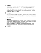
Intel Desktop Board D525MW Product Guide CAUTION Failure to ensure appropriate airflow may result in damage to these components. Ensure that the ambient temperature does not exceed the board's ... airflow is maintained around the processor, processor voltage regulator circuit, and the DIMM. Chassis venting locations are recommended over the processor, voltage regulator, and system memory areas for determining the adequacy of any thermal or system design remains solely with adequate thermal performance. CAUTION A thermal rating of both the processor and...
Intel Desktop Board D525MW Product Guide CAUTION Failure to ensure appropriate airflow may result in damage to these components. Ensure that the ambient temperature does not exceed the board's ... airflow is maintained around the processor, processor voltage regulator circuit, and the DIMM. Chassis venting locations are recommended over the processor, voltage regulator, and system memory areas for determining the adequacy of any thermal or system design remains solely with adequate thermal performance. CAUTION A thermal rating of both the processor and...

Product Guide
Page 28
... socket. Align the notch in the DIMM with the key in the socket (Figure 7, B), while holding the DIMM with all applicable Intel SDRAM memory specifications, the boards require DIMMs that support up to disengage them from the SO-DIMM. 28 Installing System...gently spread the socket's retention arms (Figure 7, C) to 4 GB of system memory. If you are installing a second DIMM, repeat Step 2 using the top (DIMM 1) socket (Figure 7, D). Intel Desktop Board D525MW Product Guide Installing and Removing Memory NOTE To be fully compliant with the back edge tilted slightly upwards, insert it in...
... socket. Align the notch in the DIMM with the key in the socket (Figure 7, B), while holding the DIMM with all applicable Intel SDRAM memory specifications, the boards require DIMMs that support up to disengage them from the SO-DIMM. 28 Installing System...gently spread the socket's retention arms (Figure 7, C) to 4 GB of system memory. If you are installing a second DIMM, repeat Step 2 using the top (DIMM 1) socket (Figure 7, D). Intel Desktop Board D525MW Product Guide Installing and Removing Memory NOTE To be fully compliant with the back edge tilted slightly upwards, insert it in...

Product Guide
Page 35
... of the serial port header. See Figure 12, D and G on page 33 for more information. Table 9. Front Panel USB Header with Intel Z-U130 USB Solid-State Drive or Compatible Device Support Pin Signal Name 1 +5 VDC 3 D- 5 D+ 7 Ground 9 KEY (no pin...9 KEY (no pin) Pin Signal Name 2 No Connect 4 No Connect 6 No Connect 8 No Connect 10 LED# 35 Refer to support a Flash Memory Drive such as the Intel Z-U130 USB Solid-State Drive (or compatible device). Installing and Replacing Desktop Board Components Connecting to the Serial Port Header Before connecting to...
... of the serial port header. See Figure 12, D and G on page 33 for more information. Table 9. Front Panel USB Header with Intel Z-U130 USB Solid-State Drive or Compatible Device Support Pin Signal Name 1 +5 VDC 3 D- 5 D+ 7 Ground 9 KEY (no pin...9 KEY (no pin) Pin Signal Name 2 No Connect 4 No Connect 6 No Connect 8 No Connect 10 LED# 35 Refer to support a Flash Memory Drive such as the Intel Z-U130 USB Solid-State Drive (or compatible device). Installing and Replacing Desktop Board Components Connecting to the Serial Port Header Before connecting to...

Product Guide
Page 41
... miljølovgivning. Installing and Replacing Desktop Board Components 12. Replacing the Battery A coin-cell battery powers the Desktop Board's real-time clock and CMOS memory. La mise au rebut des piles usagées doit respecter les réglementations locales en vigueur en matière de protection de l'environnement...
... miljølovgivning. Installing and Replacing Desktop Board Components 12. Replacing the Battery A coin-cell battery powers the Desktop Board's real-time clock and CMOS memory. La mise au rebut des piles usagées doit respecter les réglementations locales en vigueur en matière de protection de l'environnement...

Product Guide
Page 47
... the key after the Power-On Self-Test (POST) memory test begins and before the operating system boot begins. You can also save this file to view and change the BIOS settings for multiple identical systems.) 4. Go to the Intel Desktop Board D525MW page, click "[view] Latest BIOS updates," and select ...the executable file from the location on your hard drive. (You can access the BIOS Setup program by either using the Intel Express BIOS Update utility or the Iflash Memory Update utility, and how to recover the BIOS if an update fails. This step is included in the dialog boxes to...
... the key after the Power-On Self-Test (POST) memory test begins and before the operating system boot begins. You can also save this file to view and change the BIOS settings for multiple identical systems.) 4. Go to the Intel Desktop Board D525MW page, click "[view] Latest BIOS updates," and select ...the executable file from the location on your hard drive. (You can access the BIOS Setup program by either using the Intel Express BIOS Update utility or the Iflash Memory Update utility, and how to recover the BIOS if an update fails. This step is included in the dialog boxes to...

Product Guide
Page 48
...use the information in this section to update the BIOS. Intel Desktop Board D525MW Product Guide Updating the BIOS with the update utility before attempting a BIOS update. NOTE Review the instructions distributed with the Iflash Memory Update Utility You can use the F10 key option during ...BIOS update file contains: • New BIOS file • Intel Flash Memory Update Utility You can update to a new version of these files through your hard drive and copied to the Intel Desktop Board D525MW page at http://www.intel.com/p/en_US/support?iid=hdr+support . CAUTION Do not interrupt ...
...use the information in this section to update the BIOS. Intel Desktop Board D525MW Product Guide Updating the BIOS with the update utility before attempting a BIOS update. NOTE Review the instructions distributed with the Iflash Memory Update Utility You can use the F10 key option during ...BIOS update file contains: • New BIOS file • Intel Flash Memory Update Utility You can update to a new version of these files through your hard drive and copied to the Intel Desktop Board D525MW page at http://www.intel.com/p/en_US/support?iid=hdr+support . CAUTION Do not interrupt ...

Product Guide
Page 51
... to the board's line out audio jack (see Figure 2, B on the video monitor. BIOS Beep Codes Type F2 Setup/F10 Boot Menu Prompt Video error Memory error Thermal trip warning Pattern Frequency One 0.5-second beep when the BIOS is ready to signal status messages and error messages indicating recoverable errors that...
... to the board's line out audio jack (see Figure 2, B on the video monitor. BIOS Beep Codes Type F2 Setup/F10 Boot Menu Prompt Video error Memory error Thermal trip warning Pattern Frequency One 0.5-second beep when the BIOS is ready to signal status messages and error messages indicating recoverable errors that...

Product Guide
Page 52
...second pause (off . Table 17. Run Setup to boot. 52 On-off . POST Error Messages Error Message CMOS Battery Low CMOS Checksum Bad Memory Size Decreased No Boot Device Available Explanation The battery may have been corrupted. If no VGA option ROM is complete. System did not find a ... is incorrect. On-off (1.0 second each) three times, then a 2.5-second pause (off . Table 16. Each beep will be losing power. Intel Desktop Board D525MW Product Guide BIOS Front-panel Power LED Blink Codes The BIOS also blinks the front-panel power LED to signal status messages and error...
...second pause (off . Table 17. Run Setup to boot. 52 On-off . POST Error Messages Error Message CMOS Battery Low CMOS Checksum Bad Memory Size Decreased No Boot Device Available Explanation The battery may have been corrupted. If no VGA option ROM is complete. System did not find a ... is incorrect. On-off (1.0 second each) three times, then a 2.5-second pause (off . Table 16. Each beep will be losing power. Intel Desktop Board D525MW Product Guide BIOS Front-panel Power LED Blink Codes The BIOS also blinks the front-panel power LED to signal status messages and error...

Product Specification
Page 5
...Feature Summary ...9 1.1.2 Board Layout ...11 1.1.3 Block Diagram ...13 1.2 Online Support...14 1.3 Processor ...14 1.3.1 Intel® D525 Graphics Subsystem ...15 1.4 System Memory ...16 1.5 Intel® NM10 Express Chipset...17 1.5.2 USB ...19 1.5.3 SATA Support ...19 1.6 Real-Time Clock Subsystem ...20 ... Power Management ...27 1.11.1 ACPI...27 1.11.2 Hardware Support ...30 2 Technical Reference ...33 2.1 Memory Map...2.1.1 Addressable Memory...2.2 Connectors and Headers...2.2.1 Back Panel ...2.2.2 Component-side Connectors and Headers ...2.3 BIOS Configuration Jumper Block...2.4 Mechanical ...
...Feature Summary ...9 1.1.2 Board Layout ...11 1.1.3 Block Diagram ...13 1.2 Online Support...14 1.3 Processor ...14 1.3.1 Intel® D525 Graphics Subsystem ...15 1.4 System Memory ...16 1.5 Intel® NM10 Express Chipset...17 1.5.2 USB ...19 1.5.3 SATA Support ...19 1.6 Real-Time Clock Subsystem ...20 ... Power Management ...27 1.11.1 ACPI...27 1.11.2 Hardware Support ...30 2 Technical Reference ...33 2.1 Memory Map...2.1.1 Addressable Memory...2.2 Connectors and Headers...2.2.1 Back Panel ...2.2.2 Component-side Connectors and Headers ...2.3 BIOS Configuration Jumper Block...2.4 Mechanical ...

Product Specification
Page 6
vi Intel Desktop Board D525MW and Intel Desktop Board D525MWV Technical Product Specification 2.7 Power Consumption ...2.7.1 Minimum Load Configuration...2.7.2 Maximum Load Configuration ...2.8 Reliability ...2.9 Environmental ...3.1 Introduction ...3.2 BIOS Flash Memory Organization ...3.3 Resource Configuration ...3.3.1 PCI* Autoconfiguration...3.4 System Management BIOS (SMBIOS)...3.5 Legacy USB Support ...3.6 BIOS Updates ...3.6.1 BIOS Recovery...3.6.2 Custom Splash Screen ...3.7 Boot Options...3.7.1 Optical Drive Boot ...3.7.2 Network ...
vi Intel Desktop Board D525MW and Intel Desktop Board D525MWV Technical Product Specification 2.7 Power Consumption ...2.7.1 Minimum Load Configuration...2.7.2 Maximum Load Configuration ...2.8 Reliability ...2.9 Environmental ...3.1 Introduction ...3.2 BIOS Flash Memory Organization ...3.3 Resource Configuration ...3.3.1 PCI* Autoconfiguration...3.4 System Management BIOS (SMBIOS)...3.5 Legacy USB Support ...3.6 BIOS Updates ...3.6.1 BIOS Recovery...3.6.2 Custom Splash Screen ...3.7 Boot Options...3.7.1 Optical Drive Boot ...3.7.2 Network ...

Product Specification
Page 7
...Front Panel USB Header...48 Connection Diagram for Front Panel USB Header with Intel Z-U130 USB Solid-State Drive or Compatible Device Support ...44 vii Feature Summary...9 Board Components Shown in Figure 1 ...12 Supported Memory Configurations ...16 LAN Connector LED States ...22 Audio Jack Support ...23...Header ...44 Front Panel USB Header with Intel Z- USB Solid-State Drive or Compatible Device Support...48 Location of Pressing the Power Switch ...27 Power States and Targeted System Power...28 Wake-up Devices and Events ...29 System Memory Map ...35 Component-side Connectors and ...
...Front Panel USB Header...48 Connection Diagram for Front Panel USB Header with Intel Z-U130 USB Solid-State Drive or Compatible Device Support ...44 vii Feature Summary...9 Board Components Shown in Figure 1 ...12 Supported Memory Configurations ...16 LAN Connector LED States ...22 Audio Jack Support ...23...Header ...44 Front Panel USB Header with Intel Z- USB Solid-State Drive or Compatible Device Support...48 Location of Pressing the Power Switch ...27 Power States and Targeted System Power...28 Wake-up Devices and Events ...29 System Memory Map ...35 Component-side Connectors and ...
Product Specification
Page 9
... 1066 MHz, and DDR3 1333 MHz SO-DIMMs Note: DDR3 1066 MHz and DDR3 1333 MHz memory will run at 800 MHz • Support for up to 2 GB of Intel Desktop Board D525MW and Intel Desktop Board D525MWV. Table 1. 1 1.1 1.1.1 Product Description Overview Feature Summary Table 1 summarizes the... major features of system memory on a single SO-DIMM (4 GB with support for front panel cabling ― ...
... 1066 MHz, and DDR3 1333 MHz SO-DIMMs Note: DDR3 1066 MHz and DDR3 1333 MHz memory will run at 800 MHz • Support for up to 2 GB of Intel Desktop Board D525MW and Intel Desktop Board D525MWV. Table 1. 1 1.1 1.1.1 Product Description Overview Feature Summary Table 1 summarizes the... major features of system memory on a single SO-DIMM (4 GB with support for front panel cabling ― ...

Product Specification
Page 14
.../support/go/buildit 1.3 Processor The board has a passively-cooled, soldered-down Dual-Core Intel Atom processor with integrated graphics and integrated memory controller. NOTE The board is designed to Section 2.2.2.3, page 45 14 Intel Desktop Board D525MW and Intel Desktop Board D525MWV Technical Product Specification 1.2 Online Support To find information about Power supply connectors Refer...
.../support/go/buildit 1.3 Processor The board has a passively-cooled, soldered-down Dual-Core Intel Atom processor with integrated graphics and integrated memory controller. NOTE The board is designed to Section 2.2.2.3, page 45 14 Intel Desktop Board D525MW and Intel Desktop Board D525MWV Technical Product Specification 1.2 Online Support To find information about Power supply connectors Refer...

Product Specification
Page 16
Intel Desktop Board D525MW and Intel Desktop Board D525MWV Technical Product Specification 1.4 System Memory DDR3 SDRAM SO-DIMMs with DIMMs that support the Serial Presence Detect (SPD) data structure. Table 3. Supported Memory Configurations DIMM Capacity 1024 MB 1024 MB 2048 MB 2048 MB Configuration DS SS DS SS SDRAM Density 1...board should be populated with gold-plated contacts Unbuffered, single-sided or double-sided DIMMs 4 GB maximum total system memory Minimum total system memory: 256 MB Non-ECC DIMMs Serial Presence Detect DDR3 800 MHz, DDR3 1066 MHz, and DDR3 1333 MHz SO...
Intel Desktop Board D525MW and Intel Desktop Board D525MWV Technical Product Specification 1.4 System Memory DDR3 SDRAM SO-DIMMs with DIMMs that support the Serial Presence Detect (SPD) data structure. Table 3. Supported Memory Configurations DIMM Capacity 1024 MB 1024 MB 2048 MB 2048 MB Configuration DS SS DS SS SDRAM Density 1...board should be populated with gold-plated contacts Unbuffered, single-sided or double-sided DIMMs 4 GB maximum total system memory Minimum total system memory: 256 MB Non-ECC DIMMs Serial Presence Detect DDR3 800 MHz, DDR3 1066 MHz, and DDR3 1333 MHz SO...


