

Product Guide
Page 19
... wakeup support ― WAKE# signal wakeup support ― Wake from serial port ACPI ACPI gives the operating system direct control over the power management and Plug and Play functions of ACPI with the Desktop Board requires an operating system that provides full ACPI support. The use of ...a computer. Failure to the system. Desktop Board Features Power Management Features Power management is standby power to do so could damage the board and any devices connected to be off and the standby...
... wakeup support ― WAKE# signal wakeup support ― Wake from serial port ACPI ACPI gives the operating system direct control over the power management and Plug and Play functions of ACPI with the Desktop Board requires an operating system that provides full ACPI support. The use of ...a computer. Failure to the system. Desktop Board Features Power Management Features Power management is standby power to do so could damage the board and any devices connected to be off and the standby...

Product Guide
Page 23
Failure to record information about your computer, such as model, serial numbers, installed ...Always follow the steps in each procedure in the correct order. • Set up a log to disconnect power, telecommunications links, networks, or modems before performing any procedures can result in this chapter assume familiarity with the ... • Install a Wireless LAN card • Install an Intel Z-U130 USB Solid-State Drive or compatible device • Connect to internal headers • Connect chassis fan and power supply cables • Set the BIOS configuration jumper • ...
Failure to record information about your computer, such as model, serial numbers, installed ...Always follow the steps in each procedure in the correct order. • Set up a log to disconnect power, telecommunications links, networks, or modems before performing any procedures can result in this chapter assume familiarity with the ... • Install a Wireless LAN card • Install an Intel Z-U130 USB Solid-State Drive or compatible device • Connect to internal headers • Connect chassis fan and power supply cables • Set the BIOS configuration jumper • ...

Product Guide
Page 27
... can result in personal injury or equipment damage. Failure to your chassis manual for Intel Desktop Board D525MW. Figure 6 shows the location of the mounting screw holes for instructions on installing and removing the Desktop Board. Intel Desktop Board D525MW Mounting Screw Holes 27 Refer to disconnect the power before performing the procedures described here. Installing...
... can result in personal injury or equipment damage. Failure to your chassis manual for Intel Desktop Board D525MW. Figure 6 shows the location of the mounting screw holes for instructions on installing and removing the Desktop Board. Intel Desktop Board D525MW Mounting Screw Holes 27 Refer to disconnect the power before performing the procedures described here. Installing...

Product Guide
Page 38
Figure 14 shows the location of the power connectors. Connecting Power Supply Cables 1. Connect the main power supply cable to the 2 x 2 pin connector (Figure 14, A). 38 Connect the 12 V processor core voltage power supply cable to the 2 x 12 pin connector (Figure 14, B). 3. Figure 14. Observe the precautions in damage to the board or the system may not function properly. Intel Desktop Board D525MW Product Guide Connecting a Power Supply CAUTION Failure to connect an appropriate power supply to the Desktop Board may result in "Before You Begin" on page 23. 2.
Figure 14 shows the location of the power connectors. Connecting Power Supply Cables 1. Connect the main power supply cable to the 2 x 2 pin connector (Figure 14, A). 38 Connect the 12 V processor core voltage power supply cable to the 2 x 12 pin connector (Figure 14, B). 3. Figure 14. Observe the precautions in damage to the board or the system may not function properly. Intel Desktop Board D525MW Product Guide Connecting a Power Supply CAUTION Failure to connect an appropriate power supply to the Desktop Board may result in "Before You Begin" on page 23. 2.

Product Specification
Page 32
Figure 6. Failure to the board. CAUTION If AC power has been switched off . Location of the standby power indicator LED. Figure 6 shows the location of the Standby Power Indicator LED 32 Intel Desktop Board D525MW and Intel Desktop Board D525MWV Technical Product Specification 1.11.2.9 +5 V Standby Power Indicator LED The +5 V standby power indicator LED shows that power is still present even when...
Figure 6. Failure to the board. CAUTION If AC power has been switched off . Location of the standby power indicator LED. Figure 6 shows the location of the Standby Power Indicator LED 32 Intel Desktop Board D525MW and Intel Desktop Board D525MWV Technical Product Specification 1.11.2.9 +5 V Standby Power Indicator LED The +5 V standby power indicator LED shows that power is still present even when...
Product Specification
Page 58
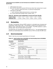
...parts requirements. Table 31. Maximum Load Configuration Current and Power Results Output Voltage Maximum Load 3.3 V 0.78 A 5V 4.84 A 12 V1 1.31 A 12 V2 0.433 A -12 V 0.03 A 5 VSB 0.243 A 2.8 Reliability The Mean Time Between Failures (MTBF) prediction is based on board peripherals enabled (...178; Half sine 2 millisecond Product weight (pounds) Free fall (inches) Intel Desktop Board D525MW and Intel Desktop Board D525MWV Technical Product Specification USB keyboard and mouse Back and front panel host-powered USB devices (other than keyboard and mouse) ⎯ Load: continuous ...
...parts requirements. Table 31. Maximum Load Configuration Current and Power Results Output Voltage Maximum Load 3.3 V 0.78 A 5V 4.84 A 12 V1 1.31 A 12 V2 0.433 A -12 V 0.03 A 5 VSB 0.243 A 2.8 Reliability The Mean Time Between Failures (MTBF) prediction is based on board peripherals enabled (...178; Half sine 2 millisecond Product weight (pounds) Free fall (inches) Intel Desktop Board D525MW and Intel Desktop Board D525MWV Technical Product Specification USB keyboard and mouse Back and front panel host-powered USB devices (other than keyboard and mouse) ⎯ Load: continuous ...


