

Product Specification
Page 6
Intel Desktop Board D525MW and Intel Desktop Board D525MWV Technical Product Specification 2.7 Power Consumption ...2.7.1 Minimum Load Configuration...2.7.2 Maximum Load Configuration ...2.8 Reliability ...2.9 Environmental ...3.1 Introduction ...3.2 BIOS Flash Memory Organization ...3.3 Resource Configuration ...3.3.1 PCI* ... Without Attached Devices...3.7.4 Changing the Default Boot Device During POST ...3.8 BIOS Security Features ...4.1 4.2 4.3 4.4 BIOS Beep Codes ...Front-panel Power LED Blink Codes ...BIOS Error Messages ...Port 80h POST Codes ... 57 57 57 58 58 59 60 60 60 61 62 63 ...
Intel Desktop Board D525MW and Intel Desktop Board D525MWV Technical Product Specification 2.7 Power Consumption ...2.7.1 Minimum Load Configuration...2.7.2 Maximum Load Configuration ...2.8 Reliability ...2.9 Environmental ...3.1 Introduction ...3.2 BIOS Flash Memory Organization ...3.3 Resource Configuration ...3.3.1 PCI* ... Without Attached Devices...3.7.4 Changing the Default Boot Device During POST ...3.8 BIOS Security Features ...4.1 4.2 4.3 4.4 BIOS Beep Codes ...Front-panel Power LED Blink Codes ...BIOS Error Messages ...Port 80h POST Codes ... 57 57 57 58 58 59 60 60 60 61 62 63 ...

Product Specification
Page 28
... settings to RAM. AC power is required. Notes: 1. 2. Service can be performed safely. Intel Desktop Board D525MW and Intel Desktop Board D525MWV Technical Product Specification 1.11.1.1 System States and Power States Under ACPI, the operating system directs all system and device power state transitions. See the ...devices are not being used in and out of low-power states based on the standby power consumption of the various system and power states. working S1 - no power except for wake-up logic. S5 - No power to the system. The operating system puts devices in ...
... settings to RAM. AC power is required. Notes: 1. 2. Service can be performed safely. Intel Desktop Board D525MW and Intel Desktop Board D525MWV Technical Product Specification 1.11.1.1 System States and Power States Under ACPI, the operating system directs all system and device power state transitions. See the ...devices are not being used in and out of low-power states based on the standby power consumption of the various system and power states. working S1 - no power except for wake-up logic. S5 - No power to the system. The operating system puts devices in ...
Product Specification
Page 57
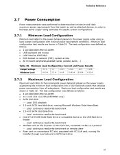
... 0.03 A 5 VSB 0.13 A 2.7.2 Maximum Load Configuration Maximum load refers to the incremental power demands placed on the power supply, augmenting the minimum load configuration into a fully-featured system that stresses power consumption from the board, as well as follows 4 GB DDR3/800 MHz SO-DIMM 14.1-inch LCD... the power demand placed on the power supply when using a bare system configuration with PCI LAN card, running Microsoft Windows Vista Home Basic ⎯ Load: continuous read/write benchmark 2.5-inch SATA hard disk drive ⎯ Load: continuous read/write benchmark Intel Z-U130...
... 0.03 A 5 VSB 0.13 A 2.7.2 Maximum Load Configuration Maximum load refers to the incremental power demands placed on the power supply, augmenting the minimum load configuration into a fully-featured system that stresses power consumption from the board, as well as follows 4 GB DDR3/800 MHz SO-DIMM 14.1-inch LCD... the power demand placed on the power supply when using a bare system configuration with PCI LAN card, running Microsoft Windows Vista Home Basic ⎯ Load: continuous read/write benchmark 2.5-inch SATA hard disk drive ⎯ Load: continuous read/write benchmark Intel Z-U130...

