

Product Guide
Page 3
... intended for installation in homes, offices, schools, computer rooms, and similar locations. may not be supported without further evaluation by Intel. Intended Audience The Product Guide is not intended for Intel® Desktop Board D525MW. Intended Uses All Intel® Desktop Boards are used in this product for other PC or embedded non-PC applications...
... intended for installation in homes, offices, schools, computer rooms, and similar locations. may not be supported without further evaluation by Intel. Intended Audience The Product Guide is not intended for Intel® Desktop Board D525MW. Intended Uses All Intel® Desktop Boards are used in this product for other PC or embedded non-PC applications...
Product Guide
Page 5
... 11 Processor ...13 System Memory 13 Integrated Graphics Subsystem 14 Intel® NM10 Express Chipset 14 Operating System Support 14 Onboard Audio Subsystem 14 Legacy Input/Output (I/O) Controller 16 LAN Subsystem 16 USB 2.0 Support 17 SATA Interface 17 Expandability...17 BIOS ...18 PCI/PCI ...Express Auto Configuration 18 Security Passwords 18 Power Management Features 19 ACPI ...19 Hardware Support 19 Battery ...22 Real-Time Clock 22 2 Installing and Replacing Desktop Board Components Before You Begin 23 Installation Precautions 25...
... 11 Processor ...13 System Memory 13 Integrated Graphics Subsystem 14 Intel® NM10 Express Chipset 14 Operating System Support 14 Onboard Audio Subsystem 14 Legacy Input/Output (I/O) Controller 16 LAN Subsystem 16 USB 2.0 Support 17 SATA Interface 17 Expandability...17 BIOS ...18 PCI/PCI ...Express Auto Configuration 18 Security Passwords 18 Power Management Features 19 ACPI ...19 Hardware Support 19 Battery ...22 Real-Time Clock 22 2 Installing and Replacing Desktop Board Components Before You Begin 23 Installation Precautions 25...

Product Guide
Page 7
... 51 16. EMC Regulations 59 20. Installing System Memory 28 8. Location of the Standby Power Indicator 20 5. Audio Jack Support 15 4. Front Panel Header Signal Names 36 12. LAN Status LEDs 16 4. Intel Desktop Board D525MW Components 12 3. POST Error Messages 52 18. Location of the Chassis Fan Header 37 14. Installing an...
... 51 16. EMC Regulations 59 20. Installing System Memory 28 8. Location of the Standby Power Indicator 20 5. Audio Jack Support 15 4. Front Panel Header Signal Names 36 12. LAN Status LEDs 16 4. Intel Desktop Board D525MW Components 12 3. POST Error Messages 52 18. Location of the Chassis Fan Header 37 14. Installing an...
Product Guide
Page 9
... ― Four back panel ports ― Three front panel ports (via two internal headers; Table 1 summarizes the features of Intel® Desktop Board D525MW. one header supports an Intel® Z-U130 USB Solid-State Drive or compatible device • Two Serial ATA (SATA) 3.0 Gb/s connectors Winbond* W83627DGH-A...PDIF digital audio header One PCI* bus add-in card connector One PCI Express* Full-Mini Card slot with support for 5.1 (6-channel) Intel® High Definition Audio (Intel® HD Audio) and AC '97 Audio. 1 Desktop Board Features This chapter briefly describes the main features...
... ― Four back panel ports ― Three front panel ports (via two internal headers; Table 1 summarizes the features of Intel® Desktop Board D525MW. one header supports an Intel® Z-U130 USB Solid-State Drive or compatible device • Two Serial ATA (SATA) 3.0 Gb/s connectors Winbond* W83627DGH-A...PDIF digital audio header One PCI* bus add-in card connector One PCI Express* Full-Mini Card slot with support for 5.1 (6-channel) Intel® High Definition Audio (Intel® HD Audio) and AC '97 Audio. 1 Desktop Board Features This chapter briefly describes the main features...
Product Guide
Page 10
.../chipsets/index.htm BIOS and driver updates http://downloadcenter.intel.com/ Integration information http://www.intel.com/support/go/buildit 10 Visit this World Wide Web site: Intel Desktop Board D525MW http://www.intel.com/products/motherboard/index.htm Desktop Board Support http://www.intel.com/p/en_US/support?iid=hdr+support Available configurations for Advanced Configuration and Power Interface (ACPI...
.../chipsets/index.htm BIOS and driver updates http://downloadcenter.intel.com/ Integration information http://www.intel.com/support/go/buildit 10 Visit this World Wide Web site: Intel Desktop Board D525MW http://www.intel.com/products/motherboard/index.htm Desktop Board Support http://www.intel.com/p/en_US/support?iid=hdr+support Available configurations for Advanced Configuration and Power Interface (ACPI...

Product Guide
Page 13
... normal operation. The Desktop Board has two 204-pin DDR3 SO-DIMM sockets with integrated graphics and memory controller. These sockets support: • Support for DDR3 800/1066/1333 MHz SO-DIMMs (DDR3 1066 MHz and DDR3 1333 MHz SO-DIMMs operate at power up.... memory • Up to configure the memory controller for maximum heat dissipation effectiveness. Desktop Board Features Processor Intel Desktop Board D525MW includes a passively-cooled, dual-core Intel Atom processor with gold-plated contacts. If your memory modules do not support SPD, you will attempt to 4 GB of memory 13
... normal operation. The Desktop Board has two 204-pin DDR3 SO-DIMM sockets with integrated graphics and memory controller. These sockets support: • Support for DDR3 800/1066/1333 MHz SO-DIMMs (DDR3 1066 MHz and DDR3 1333 MHz SO-DIMMs operate at power up.... memory • Up to configure the memory controller for maximum heat dissipation effectiveness. Desktop Board Features Processor Intel Desktop Board D525MW includes a passively-cooled, dual-core Intel Atom processor with gold-plated contacts. If your memory modules do not support SPD, you will attempt to 4 GB of memory 13

Product Guide
Page 14
... 3 • Microsoft Windows* 7 Home Basic and Starter Onboard Audio Subsystem The Intel Desktop Board D525MW 6-channel (5.1) onboard audio subsystem supports both Intel HD Audio and AC '97), including functionality for the board's I/O paths. Intel Desktop Board D525MW Product Guide Integrated Graphics Subsystem The integrated Intel GMA 3150 graphics controller features the following: • 400 MHz core frequency...
... 3 • Microsoft Windows* 7 Home Basic and Starter Onboard Audio Subsystem The Intel Desktop Board D525MW 6-channel (5.1) onboard audio subsystem supports both Intel HD Audio and AC '97), including functionality for the board's I/O paths. Intel Desktop Board D525MW Product Guide Integrated Graphics Subsystem The integrated Intel GMA 3150 graphics controller features the following: • 400 MHz core frequency...
Product Guide
Page 15
Table 3 lists the supported functions of the back panel audio connectors. Back Panel Audio Connectors NOTE The back panel audio line out connector is designed to this output. 15 ...Blue Back panel - Green Back panel - Poor audio quality occurs if passive (non-amplified) speakers are configurable through the audio device drivers. Audio Jack Support Audio Jack Front panel - Green Front panel - Pink Line In No No Yes No No Line/ Front Out Yes No No Yes No Rear Out...
Table 3 lists the supported functions of the back panel audio connectors. Back Panel Audio Connectors NOTE The back panel audio line out connector is designed to this output. 15 ...Blue Back panel - Green Back panel - Poor audio quality occurs if passive (non-amplified) speakers are configurable through the audio device drivers. Audio Jack Support Audio Jack Front panel - Green Front panel - Pink Line In No No Yes No No Line/ Front Out Yes No No Yes No Rear Out...
Product Guide
Page 16
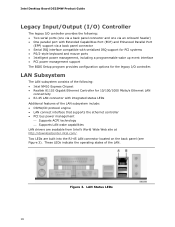
.../CD protocol engine • LAN connect interface that supports the ethernet controller • PCI bus power management ⎯ Supports ACPI technology ⎯ Supports LAN wake capabilities LAN drivers are built into the RJ-45 LAN connector located on the back panel (see Figure 3). Figure 3. Intel Desktop Board D525MW Product Guide Legacy Input/Output (I/O) Controller The...
.../CD protocol engine • LAN connect interface that supports the ethernet controller • PCI bus power management ⎯ Supports ACPI technology ⎯ Supports LAN wake capabilities LAN drivers are built into the RJ-45 LAN connector located on the back panel (see Figure 3). Figure 3. Intel Desktop Board D525MW Product Guide Legacy Input/Output (I/O) Controller The...

Product Guide
Page 17
... rate is selected. 100 Mbits/s data rate is selected. 1000 Mbits/s data rate is operating. One of the front panel USB headers supports an Intel Z-U130 USB Solid-State Drive or compatible device. USB 2.0 support requires both legacy and native modes. This may be required to the cable. SATA Interface The Desktop Board...
... rate is selected. 100 Mbits/s data rate is selected. 1000 Mbits/s data rate is operating. One of the front panel USB headers supports an Intel Z-U130 USB Solid-State Drive or compatible device. USB 2.0 support requires both legacy and native modes. This may be required to the cable. SATA Interface The Desktop Board...

Product Guide
Page 19
...; LAN Wake capabilities ― Instantly Available PC technology ― Wake from USB ― Wake from PS/2 devices ― PME# wakeup support ― WAKE# signal wakeup support ― Wake from serial port ACPI ACPI gives the operating system direct control over the power management and Plug and Play functions of... ACPI with the Desktop Board requires an operating system that provides full ACPI support. See Figure 13 on page 37 for the location of the chassis fan header. +5 V Standby Power Indicator CAUTION If the AC ...
...; LAN Wake capabilities ― Instantly Available PC technology ― Wake from USB ― Wake from PS/2 devices ― PME# wakeup support ― WAKE# signal wakeup support ― Wake from serial port ACPI ACPI gives the operating system direct control over the power management and Plug and Play functions of... ACPI with the Desktop Board requires an operating system that provides full ACPI support. See Figure 13 on page 37 for the location of the chassis fan header. +5 V Standby Power Indicator CAUTION If the AC ...

Product Guide
Page 20
... current requirements for the Desktop Board, refer to be used to wake the computer. Add-in boards that also support this specification can participate in cards and drivers. 20 Instantly Available PC Technology Instantly Available PC technology enables the board... appear to the Technical Product Specification on the Intel Desktop D525MW web page at http://www.intel.com/products/motherboard/D525MW/index.htm. Intel Desktop Board D525MW Product Guide Figure 4. Location of Instantly Available PC technology requires operating system support and PCI 2.3 compliant add-in power management ...
... current requirements for the Desktop Board, refer to be used to wake the computer. Add-in boards that also support this specification can participate in cards and drivers. 20 Instantly Available PC Technology Instantly Available PC technology enables the board... appear to the Technical Product Specification on the Intel Desktop D525MW web page at http://www.intel.com/products/motherboard/D525MW/index.htm. Intel Desktop Board D525MW Product Guide Figure 4. Location of Instantly Available PC technology requires operating system support and PCI 2.3 compliant add-in power management ...

Product Guide
Page 21
... computer wakes from an ACPI S1, S3, S4, or S5 state. NOTE Wake from an ACPI S1, S3, S4, or S5 state. WAKE# Signal Wakeup Support When the WAKE# signal is in the following ways: • By Ping • By Magic Packet Upon detecting the configured wake packet type, the LAN... Capabilities The board's LAN wake capabilities enable remote wake-up the computer. The board supports LAN wake capabilities with ACPI in an ACPI S4 or S5 state, the only PS/2 activity that supports wake from USB. PME# Wakeup Support When the PME# signal is the Alt + Print Screen key combination or the Power...
... computer wakes from an ACPI S1, S3, S4, or S5 state. NOTE Wake from an ACPI S1, S3, S4, or S5 state. WAKE# Signal Wakeup Support When the WAKE# signal is in the following ways: • By Ping • By Magic Packet Upon detecting the configured wake packet type, the LAN... Capabilities The board's LAN wake capabilities enable remote wake-up the computer. The board supports LAN wake capabilities with ACPI in an ACPI S4 or S5 state, the only PS/2 activity that supports wake from USB. PME# Wakeup Support When the PME# signal is the Alt + Print Screen key combination or the Power...

Product Guide
Page 28
...the notch in the DIMM with the key in the socket (Figure 7, B), while holding the DIMM with all applicable Intel SDRAM memory specifications, the boards require DIMMs that support up to disengage them from the SO-DIMM. 28 To install system memory on page 23. 2. Figure 7. Installing ... Board has two 204-pin DDR3 SO-DIMM sockets that support the Serial Presence Detect (SPD) data structure. Observe the precautions in "Before You Begin" on the Desktop Board, see Figure 7 and follow these steps: 1. Intel Desktop Board D525MW Product Guide Installing and Removing Memory NOTE To be fully ...
...the notch in the DIMM with the key in the socket (Figure 7, B), while holding the DIMM with all applicable Intel SDRAM memory specifications, the boards require DIMMs that support up to disengage them from the SO-DIMM. 28 To install system memory on page 23. 2. Figure 7. Installing ... Board has two 204-pin DDR3 SO-DIMM sockets that support the Serial Presence Detect (SPD) data structure. Observe the precautions in "Before You Begin" on the Desktop Board, see Figure 7 and follow these steps: 1. Intel Desktop Board D525MW Product Guide Installing and Removing Memory NOTE To be fully ...

Product Guide
Page 29
For correct cable and drive function: 1. Figure 8. The included SATA cables support the Serial ATA protocol. Attach one SATA drive. Connecting the Serial ATA Cable 29 Installing and Replacing Desktop Board Components Connecting SATA Drives The board has two SATA connectors each supporting one end of the cable to the drive (Figure 8, B). Observe the precautions in "Before You Begin" on the board (Figure 8, A) and connect the other end to the connector on page 23. 2.
For correct cable and drive function: 1. Figure 8. The included SATA cables support the Serial ATA protocol. Attach one SATA drive. Connecting the Serial ATA Cable 29 Installing and Replacing Desktop Board Components Connecting SATA Drives The board has two SATA connectors each supporting one end of the cable to the drive (Figure 8, B). Observe the precautions in "Before You Begin" on the board (Figure 8, A) and connect the other end to the connector on page 23. 2.

Product Guide
Page 32
...Align the connector (Figure 11, A) on the bottom of the cut-outs on the I/O shield. This header provides support for the solid state drive. Figure 11. Installing an Intel Z-U130 USB Solid-State Drive (or Compatible Device) 32 The connectors are keyed and will mate correctly when the ... oriented as shown in Figure 11. 3. Installing an Intel® Z-U130 USB Solid-State Drive or Compatible Device An Intel Z-U130 USB Solid-State Drive or compatible device can be installed on the Desktop Board. Intel Desktop Board D525MW Product Guide NOTE External antennas can be connected through the...
...Align the connector (Figure 11, A) on the bottom of the cut-outs on the I/O shield. This header provides support for the solid state drive. Figure 11. Installing an Intel Z-U130 USB Solid-State Drive (or Compatible Device) 32 The connectors are keyed and will mate correctly when the ... oriented as shown in Figure 11. 3. Installing an Intel® Z-U130 USB Solid-State Drive or Compatible Device An Intel Z-U130 USB Solid-State Drive or compatible device can be installed on the Desktop Board. Intel Desktop Board D525MW Product Guide NOTE External antennas can be connected through the...

Product Guide
Page 35
... (no pin) Connecting to the Front Panel USB 2.0 Headers Before connecting to support a Flash Memory Drive such as the Intel Z-U130 USB Solid-State Drive (or compatible device). Front Panel USB Header with Intel Z-U130 USB Solid-State Drive or Compatible Device Support Pin Signal Name 1 +5 VDC 3 D- 5 D+ 7 Ground 9 KEY (no pin) 10 Signal Name...
... (no pin) Connecting to the Front Panel USB 2.0 Headers Before connecting to support a Flash Memory Drive such as the Intel Z-U130 USB Solid-State Drive (or compatible device). Front Panel USB Header with Intel Z-U130 USB Solid-State Drive or Compatible Device Support Pin Signal Name 1 +5 VDC 3 D- 5 D+ 7 Ground 9 KEY (no pin) 10 Signal Name...

Product Guide
Page 47
... and before the operating system boot begins. This step is included in an automated update utility that combines the functionality of the Intel® Flash Memory Update Utility and the ease of use of Windows-based installation wizards. This runs the update program. 6. To... the BIOS settings for multiple identical systems.) 4. Go to the Intel Desktop Board D525MW page, click "[view] Latest BIOS updates," and select the Express BIOS Update utility file. 3. Navigate to http://www.intel.com/p/en_US/support?iid=hdr+support. 2. Your system will be used to complete the BIOS update...
... and before the operating system boot begins. This step is included in an automated update utility that combines the functionality of the Intel® Flash Memory Update Utility and the ease of use of Windows-based installation wizards. This runs the update program. 6. To... the BIOS settings for multiple identical systems.) 4. Go to the Intel Desktop Board D525MW page, click "[view] Latest BIOS updates," and select the Express BIOS Update utility file. 3. Navigate to http://www.intel.com/p/en_US/support?iid=hdr+support. 2. Your system will be used to complete the BIOS update...

Product Guide
Page 48
...the system may not function properly. The Iflash BIOS update file contains: • New BIOS file • Intel Flash Memory Update Utility You can update to the Intel Desktop D525MW page, click "[view] Latest BIOS updates," and select the Iflash BIOS Update utility file. Obtaining the BIOS Update... File You can obtain either of the BIOS by navigating to the Intel Desktop Board D525MW page at http://www.intel.com/p/en_US/support?iid=hdr+support . Manually run the IFLASH.EXE file from a bootable USB flash drive or other bootable USB media...
...the system may not function properly. The Iflash BIOS update file contains: • New BIOS file • Intel Flash Memory Update Utility You can update to the Intel Desktop D525MW page, click "[view] Latest BIOS updates," and select the Iflash BIOS Update utility file. Obtaining the BIOS Update... File You can obtain either of the BIOS by navigating to the Intel Desktop Board D525MW page at http://www.intel.com/p/en_US/support?iid=hdr+support . Manually run the IFLASH.EXE file from a bootable USB flash drive or other bootable USB media...

Product Guide
Page 49
... drive (with a 1.44 MB diskette) USB hard disk drive Can be Used for BIOS recovery. The BIOS recovery media does not have to http://support.intel.com/support/motherboards/desktop/sb/CS-022312.htm. 49 Yes Yes No No NOTE For more information about BIOS update and recovery, go to be damaged. however...
... drive (with a 1.44 MB diskette) USB hard disk drive Can be Used for BIOS recovery. The BIOS recovery media does not have to http://support.intel.com/support/motherboards/desktop/sb/CS-022312.htm. 49 Yes Yes No No NOTE For more information about BIOS update and recovery, go to be damaged. however...


