

Mechanical Design Guidelines
Page 3
... Thermal Management 9 1.1.2 Document Goals 9 1.1.3 Document Scope 10 1.2 References 11 1.3 Definition of Terms 11 2 Processor Thermal/Mechanical Information 13 2.1 Mechanical Requirements 13 2.1.1 Processor Package 13 2.1.2 Heatsink Attach 15 2.1.2.1 General Guidelines 15 2.1.2.2 Heatsink Clip Load Requirement 15 2.1.2.3 Additional Guidelines 16 2.2 Thermal Requirements 16 2.2.1 Processor Case Temperature 16 2.2.2 Thermal Profile 17 2.2.3 Thermal Solution Design Requirements 17 2.2.4 TCONTROL 18...
... Thermal Management 9 1.1.2 Document Goals 9 1.1.3 Document Scope 10 1.2 References 11 1.3 Definition of Terms 11 2 Processor Thermal/Mechanical Information 13 2.1 Mechanical Requirements 13 2.1.1 Processor Package 13 2.1.2 Heatsink Attach 15 2.1.2.1 General Guidelines 15 2.1.2.2 Heatsink Clip Load Requirement 15 2.1.2.3 Additional Guidelines 16 2.2 Thermal Requirements 16 2.2.1 Processor Case Temperature 16 2.2.2 Thermal Profile 17 2.2.3 Thermal Solution Design Requirements 17 2.2.4 TCONTROL 18...

Mechanical Design Guidelines
Page 4
... 5.4 Safety Requirements 47 5.5 Geometric Envelope for Intel® Reference BTX Thermal Module Assembly ......47 5.6 Preload and TMA Stiffness 48 5.6.1 Structural Design Strategy 48 5.6.2 TMA Preload verse Stiffness 48 6 ATX Thermal/Mechanical Design Information 51 6.1 ATX Reference Design Requirements 51 6.2 Validation Results for Reference Design 53 6.2.1 Heatsink Performance 53 6.2.2 Acoustics 54 6.2.3 Altitude 54...
... 5.4 Safety Requirements 47 5.5 Geometric Envelope for Intel® Reference BTX Thermal Module Assembly ......47 5.6 Preload and TMA Stiffness 48 5.6.1 Structural Design Strategy 48 5.6.2 TMA Preload verse Stiffness 48 6 ATX Thermal/Mechanical Design Information 51 6.1 ATX Reference Design Requirements 51 6.2 Validation Results for Reference Design 53 6.2.1 Heatsink Performance 53 6.2.2 Acoustics 54 6.2.3 Altitude 54...
Mechanical Design Guidelines
Page 5
Appendix A Appendix B Appendix C Appendix D Appendix E Appendix F Appendix G Appendix H 7.3 Intel® QST Configuration and Tuning 68 7.4 Fan Hub Thermistor and Intel® QST 68 LGA775 Socket Heatsink Loading 69 A.1 LGA775 Socket Heatsink Considerations 69 A.2 Metric for Heatsink Preload for ATX/uATX Designs Non-Compliant with Intel® Reference Design 69 A.3 Heatsink Preload Requirement Limitations 69 A.3.1 Motherboard Deflection Metric Definition...
Appendix A Appendix B Appendix C Appendix D Appendix E Appendix F Appendix G Appendix H 7.3 Intel® QST Configuration and Tuning 68 7.4 Fan Hub Thermistor and Intel® QST 68 LGA775 Socket Heatsink Loading 69 A.1 LGA775 Socket Heatsink Considerations 69 A.2 Metric for Heatsink Preload for ATX/uATX Designs Non-Compliant with Intel® Reference Design 69 A.3 Heatsink Preload Requirement Limitations 69 A.3.1 Motherboard Deflection Metric Definition...
Mechanical Design Guidelines
Page 6
... Package IHS Load Areas 13 Figure 2-2. Minimum Required Processor Preload to -SRM Interface Features.......50 Figure 6-1. Bottom View of Insulation on the 775-LAND LGA Package 88 Figure 7-15. Reference Clip/Heatsink Assembly 61 Figure 6-7. Digital Thermal Sensor and Thermistor 68... 7-19. Critical Core Dimension 62 Figure 7-1. Board Deflection Definition 71 Figure 7-7. Bottom View ..76 Figure 7-9. IHS Groove at 3 o'clock Exit (Old Drawing 87 Figure 7-14. Cutting Solder 94 Figure 7-26. PID Controller Fundamentals 65 Figure 7-3. Intel® QST Platform...
... Package IHS Load Areas 13 Figure 2-2. Minimum Required Processor Preload to -SRM Interface Features.......50 Figure 6-1. Bottom View of Insulation on the 775-LAND LGA Package 88 Figure 7-15. Reference Clip/Heatsink Assembly 61 Figure 6-7. Digital Thermal Sensor and Thermistor 68... 7-19. Critical Core Dimension 62 Figure 7-1. Board Deflection Definition 71 Figure 7-7. Bottom View ..76 Figure 7-9. IHS Groove at 3 o'clock Exit (Old Drawing 87 Figure 7-14. Cutting Solder 94 Figure 7-26. PID Controller Fundamentals 65 Figure 7-3. Intel® QST Platform...
Mechanical Design Guidelines
Page 7
... Extended (BTX) Type II Reference TMA Performance39 Table 5-2. Acoustic Targets 40 Table 5-3. Intel® Representative Contact for Licensing Information of Intel® Boxed Processor Thermal Solutions.22 Table 5-1. Figure 7-27. Sheet 1 113 Figure 7-44. BTX ...Thermal Module Keep Out Volumetric - Sheet 2 121 Figure 7-52. Thermal sensor Location Illustration 105 Figure 7-40. BTX Thermal Module Keep Out Volumetric - Sheet 5 117 Figure 7-48. Heatsink...
... Extended (BTX) Type II Reference TMA Performance39 Table 5-2. Acoustic Targets 40 Table 5-3. Intel® Representative Contact for Licensing Information of Intel® Boxed Processor Thermal Solutions.22 Table 5-1. Figure 7-27. Sheet 1 113 Figure 7-44. BTX ...Thermal Module Keep Out Volumetric - Sheet 2 121 Figure 7-52. Thermal sensor Location Illustration 105 Figure 7-40. BTX Thermal Module Keep Out Volumetric - Sheet 5 117 Figure 7-48. Heatsink...

Mechanical Design Guidelines
Page 11
...be beneficial when reading this document. Document Intel® Core™2 Duo Processor E8000 and E7000 Series Datasheet Intel® Pentium® Dual-Core Processor E6000 and E5000 Series Datasheet Intel® Celeron® Processor E3000 Series Datasheet LGA775 Socket Mechanical Design ... temperature locally surrounding the processor. Case-to a system chassis. Material and concepts available in a component specification. The ambient temperature should be specified for an active heatsink. Heatsink temperature measured on the underside of a passive heatsink or at a location ...
...be beneficial when reading this document. Document Intel® Core™2 Duo Processor E8000 and E7000 Series Datasheet Intel® Pentium® Dual-Core Processor E6000 and E5000 Series Datasheet Intel® Celeron® Processor E3000 Series Datasheet LGA775 Socket Mechanical Design ... temperature locally surrounding the processor. Case-to a system chassis. Material and concepts available in a component specification. The ambient temperature should be specified for an active heatsink. Heatsink temperature measured on the underside of a passive heatsink or at a location ...

Mechanical Design Guidelines
Page 12
... / Total Package Power. Note: Heat source must be expressed as a dimension away from the processor case to the heatsink. The maximum power dissipated by lowering the effective processor frequency when the die temperature has exceeded its operating limits. Thermal solutions should be specified for &#... thermal diode. A measure of PROCHOT#. This is the area between the heatsink and the processor case. Thermal Control Circuit: Thermal Monitor uses the TCC to -ambient thermal characterization parameter. The heatsink, fan and duct assembly for use the PWM duty cycle % from the...
... / Total Package Power. Note: Heat source must be expressed as a dimension away from the processor case to the heatsink. The maximum power dissipated by lowering the effective processor frequency when the die temperature has exceeded its operating limits. Thermal solutions should be specified for &#... thermal diode. A measure of PROCHOT#. This is the area between the heatsink and the processor case. Thermal Control Circuit: Thermal Monitor uses the TCC to -ambient thermal characterization parameter. The heatsink, fan and duct assembly for use the PWM duty cycle % from the...

Mechanical Design Guidelines
Page 14
... static load is necessary to ensure thermal performance of the thermal interface material between the heatsink base and the IHS, it should not exceed the corresponding specification given in the processor datasheet. • When a compressive static load is necessary to ensure mechanical performance, it... should not be taken into account in the processor datasheet. For example, with a 0.550 kg [1.2 lb] heatsink, an acceleration of 50G during an 11 ms trapezoidal shock with the seating plane of the socket. The...
... static load is necessary to ensure thermal performance of the thermal interface material between the heatsink base and the IHS, it should not exceed the corresponding specification given in the processor datasheet. • When a compressive static load is necessary to ensure mechanical performance, it... should not be taken into account in the processor datasheet. For example, with a 0.550 kg [1.2 lb] heatsink, an acceleration of 50G during an 11 ms trapezoidal shock with the seating plane of the socket. The...

Mechanical Design Guidelines
Page 15
Processor Thermal/Mechanical Information 2.1.2 Heatsink Attach 2.1.2.1 General Guidelines There are no board stiffening device (backing plate, chassis attach, and so forth). TIMs such as thermal greases are very sensitive to ... socket load plate (refer to the LGA775 Socket Mechanical Design Guide for further information). 2.1.2.2 Heatsink Clip Load Requirement The attach mechanism for the heatsink developed to support the processor should create a static preload on the mass of the heatsink and the level of the motherboard and the system have to Figure 7-40) • TMA...
Processor Thermal/Mechanical Information 2.1.2 Heatsink Attach 2.1.2.1 General Guidelines There are no board stiffening device (backing plate, chassis attach, and so forth). TIMs such as thermal greases are very sensitive to ... socket load plate (refer to the LGA775 Socket Mechanical Design Guide for further information). 2.1.2.2 Heatsink Clip Load Requirement The attach mechanism for the heatsink developed to support the processor should create a static preload on the mass of the heatsink and the level of the motherboard and the system have to Figure 7-40) • TMA...

Mechanical Design Guidelines
Page 16
... chassis. • Minimizes contact with a 28.7 mm x 28.7 mm [1.13 in x 1.13 in] IHS top surface. Processor Thermal/Mechanical Information 2.1.2.3 Additional Guidelines In addition to the general guidelines given above, the heatsink attach mechanism for the processor should be dissipated as a function of power being dissipated. Note that the load applied by the...
... chassis. • Minimizes contact with a 28.7 mm x 28.7 mm [1.13 in x 1.13 in] IHS top surface. Processor Thermal/Mechanical Information 2.1.2.3 Additional Guidelines In addition to the general guidelines given above, the heatsink attach mechanism for the processor should be dissipated as a function of power being dissipated. Note that the load applied by the...
Mechanical Design Guidelines
Page 17
...function in ATX Chassis, with the available chassis solutions. The slope of the Intel reference design. For an example of Intel Core™2 Duo processor E8000 series with 6 MB in thermal solution performance of the thermal profile ...was established assuming a generational improvement in ATX platform, its intended target thermal environment, thermal solutions that are targeted to function in an environment that is consistent with a fan installed at the top of the heatsink...
...function in ATX Chassis, with the available chassis solutions. The slope of the Intel reference design. For an example of Intel Core™2 Duo processor E8000 series with 6 MB in thermal solution performance of the thermal profile ...was established assuming a generational improvement in ATX platform, its intended target thermal environment, thermal solutions that are targeted to function in an environment that is consistent with a fan installed at the top of the heatsink...

Mechanical Design Guidelines
Page 19
... thermal performance depends on reading the register and calculating TCONTROL. These heatsinks are therefore typically larger (and heavier) than active heatsinks due to it. See Chapter 7, Intel® Quiet System Technology (Intel® QST), for further details on its thermal conductivity as well as processor cooling requirements become stricter. One method used to improve thermal...
... thermal performance depends on reading the register and calculating TCONTROL. These heatsinks are therefore typically larger (and heavier) than active heatsinks due to it. See Chapter 7, Intel® Quiet System Technology (Intel® QST), for further details on its thermal conductivity as well as processor cooling requirements become stricter. One method used to improve thermal...

Mechanical Design Guidelines
Page 20
...Guide found at http://www.formfactors.org/. The target height of interest. Heatsink Mass With the need to push air cooling to better performance, heatsink solutions tend to increase heatsink thermal conduction performance results in even heavier solutions. Processor Thermal/Mechanical Information 2.3.1 2.3.2 required to the form factor requirements, while ... for example) as well as other BTX system considerations for controlling airflow through it in a system and by the processor heatsink. Heatsink Size The size of other design considerations (air duct, and so forth).
...Guide found at http://www.formfactors.org/. The target height of interest. Heatsink Mass With the need to push air cooling to better performance, heatsink solutions tend to increase heatsink thermal conduction performance results in even heavier solutions. Processor Thermal/Mechanical Information 2.3.1 2.3.2 required to the form factor requirements, while ... for example) as well as other BTX system considerations for controlling airflow through it in a system and by the processor heatsink. Heatsink Size The size of other design considerations (air duct, and so forth).

Mechanical Design Guidelines
Page 21
... positional alignment when selecting the proper thermal interface material size. ATX Designs that ensures the entire processor IHS area is 550g. Intel recommends testing and validating heatsink performance in the datasheet and can be sized and positioned on the capabilities of the clip and fastener in Appendix A and retention limits of the ...
... positional alignment when selecting the proper thermal interface material size. ATX Designs that ensures the entire processor IHS area is 550g. Intel recommends testing and validating heatsink performance in the datasheet and can be sized and positioned on the capabilities of the clip and fastener in Appendix A and retention limits of the ...
Mechanical Design Guidelines
Page 22
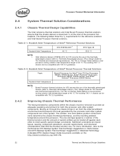
... Considerations 2.4.1 Chassis Thermal Design Capabilities The Intel reference thermal solutions and Intel Boxed Processor thermal solutions assume that limit the thermal solution size. The following tables show the TA requirements for Intel® Core™2 Duo Processor E8000, E7000 Series, Intel® Pentium® Dual-Core Processor E6000, E5000 Series, and Intel® Celeron® Processor E3000 Series Heatsink Inlet Temperature 40 °C NOTE: 1.
... Considerations 2.4.1 Chassis Thermal Design Capabilities The Intel reference thermal solutions and Intel Boxed Processor thermal solutions assume that limit the thermal solution size. The following tables show the TA requirements for Intel® Core™2 Duo Processor E8000, E7000 Series, Intel® Pentium® Dual-Core Processor E6000, E5000 Series, and Intel® Celeron® Processor E3000 Series Heatsink Inlet Temperature 40 °C NOTE: 1.
Mechanical Design Guidelines
Page 23
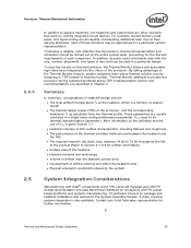
... system implementation. Contact your Intel field sales representative for all capable of the processor. By taking advantage of the Thermal Monitor feature, system designers may be used between the heatsink and the IHS. • The required heatsink clip static load, between ... further information). • Surface area of the heatsink. • Heatsink material and technology. • Volume of airflow over the heatsink surface area. • Development of fans that exist for the thermal requirements of the processor, and the corresponding maximum TC as calculated from ...
... system implementation. Contact your Intel field sales representative for all capable of the processor. By taking advantage of the Thermal Monitor feature, system designers may be used between the heatsink and the IHS. • The required heatsink clip static load, between ... further information). • Surface area of the heatsink. • Heatsink material and technology. • Volume of airflow over the heatsink surface area. • Development of fans that exist for the thermal requirements of the processor, and the corresponding maximum TC as calculated from ...

Mechanical Design Guidelines
Page 25
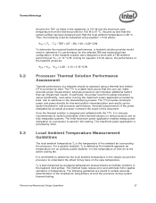
... ΨCS = Thermal characterization parameter of the thermal interface material (°C/W) ΨSA = Thermal characterization parameter from heatsink-to compare thermal solutions in identical situations (same heat source and local ambient conditions). The case-to-local ambient thermal characterization...parameter", Ψ ("psi"), is a convenient way to characterize the performance needed for testing thermal solutions, including measuring processor temperatures. Thermal Metrology 3 Thermal Metrology This section discusses guidelines for the thermal solution and to -local ambient (°...
... ΨCS = Thermal characterization parameter of the thermal interface material (°C/W) ΨSA = Thermal characterization parameter from heatsink-to compare thermal solutions in identical situations (same heat source and local ambient conditions). The case-to-local ambient thermal characterization...parameter", Ψ ("psi"), is a convenient way to characterize the performance needed for testing thermal solutions, including measuring processor temperatures. Thermal Metrology 3 Thermal Metrology This section discusses guidelines for the thermal solution and to -local ambient (°...

Mechanical Design Guidelines
Page 26
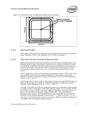
... illustration of the different thermal characterization parameters. Since the processor thermal profile applies to all processor frequencies, it is dependent on the air velocity through the fins of the heatsink. The example power and temperature numbers used here are not related to any specific Intel processor thermal specifications, and are for a targeted chassis characterized by...
... illustration of the different thermal characterization parameters. Since the processor thermal profile applies to all processor frequencies, it is dependent on the air velocity through the fins of the heatsink. The example power and temperature numbers used here are not related to any specific Intel processor thermal specifications, and are for a targeted chassis characterized by...
Mechanical Design Guidelines
Page 27
... meant to determine the local ambient temperature in the manufacturing process. If the heatsink solution were designed to work with the TTV, it is the temperature of the thermal solution on real processors and on fully integrated systems. The Intel maximum power application enables steady power dissipation on the case temperature. for thermal...
... meant to determine the local ambient temperature in the manufacturing process. If the heatsink solution were designed to work with the TTV, it is the temperature of the thermal solution on real processors and on fully integrated systems. The Intel maximum power application enables steady power dissipation on the case temperature. for thermal...

Mechanical Design Guidelines
Page 28
..., when doing a bench top test at room temperature, the fan regulation prevents the heatsink from processor and heatsink as shown in the ATX heatsink in Figure 3-2 (avoiding the hub spokes). Thermal Metrology For active heatsinks, it is used, it may be useful to add a thermocouple taped to the barrier...For even more realistic airflow, the motherboard should be useful, and usually ensures more uniform temperatures at the fan inlet. For passive heatsinks, thermocouples should be done in a thermal chamber to avoid taking measurement in the dead flow zone that usually develops above the test ...
..., when doing a bench top test at room temperature, the fan regulation prevents the heatsink from processor and heatsink as shown in the ATX heatsink in Figure 3-2 (avoiding the hub spokes). Thermal Metrology For active heatsinks, it is used, it may be useful to add a thermocouple taped to the barrier...For even more realistic airflow, the motherboard should be useful, and usually ensures more uniform temperatures at the fan inlet. For passive heatsinks, thermocouples should be done in a thermal chamber to avoid taking measurement in the dead flow zone that usually develops above the test ...