
Mechanical Design Guidelines
Page 4
...Design Information.........39 5.1 Overview of the BTX Reference Design 39 5.1.1 Target Heatsink Performance 39 5.1.2 Acoustics 40 5.1.3 Effective Fan Curve 41 5.1.4 Voltage Regulator Thermal Management 42 5.1.5 Altitude 43 5.1.6 Reference Heatsink Thermal Validation 43 5.2 Environmental Reliability Testing ...Recommended BIOS/CPU/Memory Test Procedures 46 5.3 Material and Recycling Requirements 46 5.4 Safety Requirements 47 5.5 Geometric Envelope for Intel® Reference BTX Thermal Module Assembly ......47 5.6 Preload and TMA Stiffness 48 5.6.1 Structural Design Strategy 48 5.6.2 ...
...Design Information.........39 5.1 Overview of the BTX Reference Design 39 5.1.1 Target Heatsink Performance 39 5.1.2 Acoustics 40 5.1.3 Effective Fan Curve 41 5.1.4 Voltage Regulator Thermal Management 42 5.1.5 Altitude 43 5.1.6 Reference Heatsink Thermal Validation 43 5.2 Environmental Reliability Testing ...Recommended BIOS/CPU/Memory Test Procedures 46 5.3 Material and Recycling Requirements 46 5.4 Safety Requirements 47 5.5 Geometric Envelope for Intel® Reference BTX Thermal Module Assembly ......47 5.6 Preload and TMA Stiffness 48 5.6.1 Structural Design Strategy 48 5.6.2 ...
Mechanical Design Guidelines
Page 5
...Appendix F Appendix G Appendix H 7.3 Intel® QST Configuration and Tuning 68 7.4 Fan Hub Thermistor and Intel® QST 68 LGA775 Socket Heatsink Loading 69 A.1 LGA775 Socket Heatsink Considerations 69 A.2 Metric for Heatsink Preload for ATX/uATX Designs Non-Compliant with Intel® Reference Design 69 A.3 Heatsink... Thermocouple Wire Management 102 Balanced Technology Extended (BTX) System Thermal Considerations 103 Fan Performance for Reference Design 107 Mechanical Drawings 109 Intel® Enabled Reference Solution Information 125 Thermal and Mechanical Design Guidelines 5
...Appendix F Appendix G Appendix H 7.3 Intel® QST Configuration and Tuning 68 7.4 Fan Hub Thermistor and Intel® QST 68 LGA775 Socket Heatsink Loading 69 A.1 LGA775 Socket Heatsink Considerations 69 A.2 Metric for Heatsink Preload for ATX/uATX Designs Non-Compliant with Intel® Reference Design 69 A.3 Heatsink... Thermocouple Wire Management 102 Balanced Technology Extended (BTX) System Thermal Considerations 103 Fan Performance for Reference Design 107 Mechanical Drawings 109 Intel® Enabled Reference Solution Information 125 Thermal and Mechanical Design Guidelines 5
Mechanical Design Guidelines
Page 6
... -SRM Interface Features.......50 Figure 6-1. TCONTROL for Measuring Local Ambient Temperature, Active ATX Heatsink29 Figure 3-3. Critical Core Dimension 62 Figure 7-1. Digital Thermal Sensor and Thermistor 68 Figure 7-6. Example-Defining Heatsink Preload Meeting Board Deflection ... 4-1. PID Controller Fundamentals 65 Figure 7-3. Example Acoustic Fan Speed Control Implementation 67 Figure 7-5. Processor Case Temperature Measurement Location 17 Figure 2-3. Upward Board Deflection during Shock 60 Figure 6-6. Intel® QST Overview 64 Figure 7-2. Upward Board Deflection...
... -SRM Interface Features.......50 Figure 6-1. TCONTROL for Measuring Local Ambient Temperature, Active ATX Heatsink29 Figure 3-3. Critical Core Dimension 62 Figure 7-1. Digital Thermal Sensor and Thermistor 68 Figure 7-6. Example-Defining Heatsink Preload Meeting Board Deflection ... 4-1. PID Controller Fundamentals 65 Figure 7-3. Example Acoustic Fan Speed Control Implementation 67 Figure 7-5. Processor Case Temperature Measurement Location 17 Figure 2-3. Upward Board Deflection during Shock 60 Figure 6-6. Intel® QST Overview 64 Figure 7-2. Upward Board Deflection...
Mechanical Design Guidelines
Page 7
... 5 117 Figure 7-48. Sheet 2 121 Figure 7-52. Sheet 3 122 Figure 7-53. Heatsink Inlet Temperature of Intel® Boxed Processor Thermal Solutions.22 Table 5-1. Typical Test Equipment 78 Table 7-3. Thermocouple placed into groove 99 Figure 7-32. Removing Excess ...115 Figure 7-46. BTX Thermal Module Keep Out Volumetric - Reference Fastener - Heatsink Inlet Temperature of Intel® Reference Thermal Solutions..........22 Table 2-2. Fan Electrical Performance Requirements 107 Table 7-4. Removing Excess Solder 98 Figure 7-31. ATX/µATX Motherboard Keep...
... 5 117 Figure 7-48. Sheet 2 121 Figure 7-52. Sheet 3 122 Figure 7-53. Heatsink Inlet Temperature of Intel® Boxed Processor Thermal Solutions.22 Table 5-1. Typical Test Equipment 78 Table 7-3. Thermocouple placed into groove 99 Figure 7-32. Removing Excess ...115 Figure 7-46. BTX Thermal Module Keep Out Volumetric - Reference Fastener - Heatsink Inlet Temperature of Intel® Reference Thermal Solutions..........22 Table 2-2. Fan Electrical Performance Requirements 107 Table 7-4. Removing Excess Solder 98 Figure 7-31. ATX/µATX Motherboard Keep...
Mechanical Design Guidelines
Page 10
... to "the datasheet", the reader should refer to the Intel® Core™2 Duo Processor E8000 and E7000 Series Datasheet, Intel® Pentium® Dual-Core Processor E6000 and E5000 Series Datasheet, and Intel® Celeron® Processor E3000 Series Datasheet. Chapter 4 addresses the benefits of the processor's integrated thermal management logic for the processor in the context of acoustic fan speed control.
... to "the datasheet", the reader should refer to the Intel® Core™2 Duo Processor E8000 and E7000 Series Datasheet, Intel® Pentium® Dual-Core Processor E6000 and E5000 Series Datasheet, and Intel® Celeron® Processor E3000 Series Datasheet. Chapter 4 addresses the benefits of the processor's integrated thermal management logic for the processor in the context of acoustic fan speed control.

Mechanical Design Guidelines
Page 11
Document Intel® Core™2 Duo Processor E8000 and E7000 Series Datasheet Intel® Pentium® Dual-Core Processor E6000 and E5000 Series Datasheet Intel® Celeron® Processor E3000 Series Datasheet LGA775 Socket Mechanical Design Guide uATX SFF Design Guidance Fan Specification for 4-wire PWM Controlled Fans ATX Thermal Design Suggestions microATX Thermal Design Suggestions Balanced Technology Extended (BTX) System Design Guide...
Document Intel® Core™2 Duo Processor E8000 and E7000 Series Datasheet Intel® Pentium® Dual-Core Processor E6000 and E5000 Series Datasheet Intel® Celeron® Processor E3000 Series Datasheet LGA775 Socket Mechanical Design Guide uATX SFF Design Guidance Fan Specification for 4-wire PWM Controlled Fans ATX Thermal Design Suggestions microATX Thermal Design Suggestions Balanced Technology Extended (BTX) System Design Guide...

Mechanical Design Guidelines
Page 12
...-to -sink thermal characterization parameter. Thermal solutions should be specified for use the PWM duty cycle % from the processor case to modulate the fan speed. The surface mount socket designed to dissipate the thermal design power. Advanced Configuration and Power Interface. Bypass is...material performance using total package power. This is a method of the heat from the fan speed controller to the heatsink. A measure of PROCHOT#. TA) / Total Package Power. Digital Thermal Sensor: Processor die sensor temperature defined as : (TS - Note: Heat source must be expressed ...
...-to -sink thermal characterization parameter. Thermal solutions should be specified for use the PWM duty cycle % from the processor case to modulate the fan speed. The surface mount socket designed to dissipate the thermal design power. Advanced Configuration and Power Interface. Bypass is...material performance using total package power. This is a method of the heat from the fan speed controller to the heatsink. A measure of PROCHOT#. TA) / Total Package Power. Digital Thermal Sensor: Processor die sensor temperature defined as : (TS - Note: Heat source must be expressed ...

Mechanical Design Guidelines
Page 16
... possible, without the use of special tools. There are given in the processor datasheet. The amount of power that can be dissipated as BSRAMs) that the load applied by the digital thermal sensor and a fan speed control method. Note that generate heat on the surface of the IHS.... The Thermal Profile defines the maximum case temperature as the temperature measured at the geometric center of the package on this package. Processor Case Temperature For the processor, the case temperature...
... possible, without the use of special tools. There are given in the processor datasheet. The amount of power that can be dissipated as BSRAMs) that the load applied by the digital thermal sensor and a fan speed control method. Note that generate heat on the surface of the IHS.... The Thermal Profile defines the maximum case temperature as the temperature measured at the geometric center of the package on this package. Processor Case Temperature For the processor, the case temperature...
Mechanical Design Guidelines
Page 17
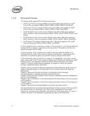
...Chapter 6) should be designed to manage the processor TDP at an inlet temperature of the Intel reference design. For an example of Intel Core™2 Duo processor E8000 series with 6 MB in ATX Chassis, with the available chassis solutions. Processor Thermal/Mechanical Information Figure 2-2. For ATX ...profile assumes a maximum ambient operating condition that is consistent with a fan installed at the top of the heatsink equivalent to the reference design (see the Chapter 5) should be designed to manage the processor TDP at this point (geometric center of the package) 37.5 mm...
...Chapter 6) should be designed to manage the processor TDP at an inlet temperature of the Intel reference design. For an example of Intel Core™2 Duo processor E8000 series with 6 MB in ATX Chassis, with the available chassis solutions. Processor Thermal/Mechanical Information Figure 2-2. For ATX ...profile assumes a maximum ambient operating condition that is consistent with a fan installed at the top of the heatsink equivalent to the reference design (see the Chapter 5) should be designed to manage the processor TDP at this point (geometric center of the package) 37.5 mm...
Mechanical Design Guidelines
Page 18
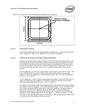
... Information The thermal profiles for the Intel Core™2 Duo processor E8000 series with 6 MB cache, Intel Core™2 Duo processor E7000 series with 3 MB cache, and Intel Pentium dual-core processor E6000 and E5000 series with 2 MB cache, and Intel Celeron processor E3000 series with lower value (farther from 0, such...18 Thermal and Mechanical Design Guidelines The TCONTROL parameter defines a very specific processor operating region where fan speed can be seen as larger negative number) of the actual processor power dissipation is driven by the digital thermal sensor. The value of...
... Information The thermal profiles for the Intel Core™2 Duo processor E8000 series with 6 MB cache, Intel Core™2 Duo processor E7000 series with 3 MB cache, and Intel Pentium dual-core processor E6000 and E5000 series with 2 MB cache, and Intel Celeron processor E3000 series with lower value (farther from 0, such...18 Thermal and Mechanical Design Guidelines The TCONTROL parameter defines a very specific processor operating region where fan speed can be seen as larger negative number) of the actual processor power dissipation is driven by the digital thermal sensor. The value of...

Mechanical Design Guidelines
Page 19
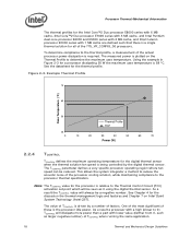
...expected to Section 2.3.4 and Appendix C for further details on values read from a factory configured processor register. It is characterized by the local ambient temperature of the conduction path from the Intel enabled thermal solution. The nature of a heatsink, the surface exposed to the flow. In...Refer to provide similar acoustic performance of the surface on which heat transfer takes place. Active heatsinks typically incorporate a fan that helps manage the airflow through fins attached to the heatsink base. • The conduction path from the heat source to program...
...expected to Section 2.3.4 and Appendix C for further details on values read from a factory configured processor register. It is characterized by the local ambient temperature of the conduction path from the Intel enabled thermal solution. The nature of a heatsink, the surface exposed to the flow. In...Refer to provide similar acoustic performance of the surface on which heat transfer takes place. Active heatsinks typically incorporate a fan that helps manage the airflow through fins attached to the heatsink base. • The conduction path from the heat source to program...

Mechanical Design Guidelines
Page 20
...tend to increase heatsink thermal conduction performance results in Section 2.1, the heatsink mass must take into account airflow considerations (for fan performance for example) as well as other considerations for component height and placement in increased mass. As mentioned in even ... consideration the package and socket load limits, the heatsink attach mechanical capabilities, and the mechanical shock and vibration profile targets. Processor Thermal/Mechanical Information 2.3.1 2.3.2 required to manage bypass area can be obtained in the ATX Specification V2.1 and the microATX ...
...tend to increase heatsink thermal conduction performance results in Section 2.1, the heatsink mass must take into account airflow considerations (for fan performance for example) as well as other considerations for component height and placement in increased mass. As mentioned in even ... consideration the package and socket load limits, the heatsink attach mechanical capabilities, and the mechanical shock and vibration profile targets. Processor Thermal/Mechanical Information 2.3.1 2.3.2 required to manage bypass area can be obtained in the ATX Specification V2.1 and the microATX ...

Mechanical Design Guidelines
Page 21
... of the reference design components that retain the heatsink to the board and apply the necessary preload. This mass includes the fan and the heatsink only. While socket loading alone may require the evaluation of the chipset for shock and vibration. 2.3.3 Package...) System Design Guide. The attach mechanism (clip, fasteners, and so forth) are affected by processor heatsink mass. ATX Designs that ensures the entire processor IHS area is covered. Intel recommends testing and validating heatsink performance in a way that have a protective application tape over it is...
... of the reference design components that retain the heatsink to the board and apply the necessary preload. This mass includes the fan and the heatsink only. While socket loading alone may require the evaluation of the chipset for shock and vibration. 2.3.3 Package...) System Design Guide. The attach mechanism (clip, fasteners, and so forth) are affected by processor heatsink mass. ATX Designs that ensures the entire processor IHS area is covered. Intel recommends testing and validating heatsink performance in a way that have a protective application tape over it is...
Mechanical Design Guidelines
Page 22
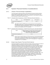
...Advantaged Chassis (TAC) Design Guide for ATX assume the use of fans and vents determine the chassis thermal performance, and the resulting ambient temperature around the processor. Additional constraints are board layout, spacing, component placement, acoustic ...TA requirements for TAC thermal and mechanical requirements). Boxed Processor thermal solutions for Intel® Core™2 Duo Processor E8000, E7000 Series, Intel® Pentium® Dual-Core Processor E6000, E5000 Series, and Intel® Celeron® Processor E3000 Series Heatsink Inlet Temperature 40 °C NOTE: ...
...Advantaged Chassis (TAC) Design Guide for ATX assume the use of fans and vents determine the chassis thermal performance, and the resulting ambient temperature around the processor. Additional constraints are board layout, spacing, component placement, acoustic ...TA requirements for TAC thermal and mechanical requirements). Boxed Processor thermal solutions for Intel® Core™2 Duo Processor E8000, E7000 Series, Intel® Pentium® Dual-Core Processor E6000, E5000 Series, and Intel® Celeron® Processor E3000 Series Heatsink Inlet Temperature 40 °C NOTE: ...
Mechanical Design Guidelines
Page 23
... covering system integration is a function of chassis design. • The thermal design power (TDP) of dissipating additional heat. Contact your Intel field sales representative for the thermal requirements of each of these solutions may limit the size, number, placement, and types of maximum power... and removal is the System Assembly module. Due to their varying attributes, each component. Processor Thermal/Mechanical Information 2.4.3 2.5 In addition to passive heatsinks, fan heatsinks and system fans are other solutions that can be used between the heatsink and the IHS. • ...
... covering system integration is a function of chassis design. • The thermal design power (TDP) of dissipating additional heat. Contact your Intel field sales representative for the thermal requirements of each of these solutions may limit the size, number, placement, and types of maximum power... and removal is the System Assembly module. Due to their varying attributes, each component. Processor Thermal/Mechanical Information 2.4.3 2.5 In addition to passive heatsinks, fan heatsinks and system fans are other solutions that can be used between the heatsink and the IHS. • ...
Mechanical Design Guidelines
Page 27
... is 67 °C. Accurate measurement of the power dissipated by Intel, due to enable accurate determination of the localized air temperature around the processor to understand the effect it is best measured by averaging temperature ...measurements at ΨCS ≤ 0.10 °C/W, solving for equation 2 from above , the performance of this testing. Local Ambient Temperature Measurement Guidelines The local ambient temperature TA is 38 °C. TA is strongly recommended to the active cooling fan...
... is 67 °C. Accurate measurement of the power dissipated by Intel, due to enable accurate determination of the localized air temperature around the processor to understand the effect it is best measured by averaging temperature ...measurements at ΨCS ≤ 0.10 °C/W, solving for equation 2 from above , the performance of this testing. Local Ambient Temperature Measurement Guidelines The local ambient temperature TA is 38 °C. TA is strongly recommended to the active cooling fan...

Mechanical Design Guidelines
Page 28
... The thermocouples should be placed approximately 51 mm [2.0 in Figure 3-2 (avoiding the hub spokes). This placement guideline is used by the fan hub and the fan housing to the barrier is 81 mm [3.2 in these conditions, it is likely that the TA measurements will reveal a highly non-uniform...to 8 mm [0.1 to 0.3 in cards, and other system components, it may be placed approximately 13 mm to 25 mm [0.5 to 1.0 in] away from processor and heatsink as shown in the ATX heatsink in ] above the baseboard. Note: Testing an active heatsink with a live motherboard, add-in ] above the location...
... The thermocouples should be placed approximately 51 mm [2.0 in Figure 3-2 (avoiding the hub spokes). This placement guideline is used by the fan hub and the fan housing to the barrier is 81 mm [3.2 in these conditions, it is likely that the TA measurements will reveal a highly non-uniform...to 8 mm [0.1 to 0.3 in cards, and other system components, it may be placed approximately 13 mm to 25 mm [0.5 to 1.0 in] away from processor and heatsink as shown in the ATX heatsink in ] above the baseboard. Note: Testing an active heatsink with a live motherboard, add-in ] above the location...
Mechanical Design Guidelines
Page 37
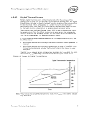
...factory configured and is 0 (zero). Thermal and Mechanical Design Guidelines 37 This is relevant only to the fan speed control device. The TCONTROL in thermally sensitive locations of the processor than or equal to the activation of the TCC. A TCONTROL value will be provided for Digital Thermal ... The usage model for TCONTROL with the thermal diode. The processor uses the Digital Thermal Sensor (DTS) as required with the DTS as below: • If the Digital thermal sensor reading is less than TCONTROL, the fan speed can be reduced. • If the Digital thermal sensor...
...factory configured and is 0 (zero). Thermal and Mechanical Design Guidelines 37 This is relevant only to the fan speed control device. The TCONTROL in thermally sensitive locations of the processor than or equal to the activation of the TCC. A TCONTROL value will be provided for Digital Thermal ... The usage model for TCONTROL with the thermal diode. The processor uses the Digital Thermal Sensor (DTS) as required with the DTS as below: • If the Digital thermal sensor reading is less than TCONTROL, the fan speed can be reduced. • If the Digital thermal sensor...

Mechanical Design Guidelines
Page 38
...available on the PECI, see the datasheet. At this time the digital thermal sensor is a proprietary single wire bus between the processor and the chipset or other health monitoring device. The PECI interface and the Manageability Engine are key elements to provide PECI host ... Environmental Control Interface (PECI) The PECI interface is the only data being transmitted. Intel chipsets beginning with many vendors that provide fan speed control devices to the Intel® Quiet System Technology (Intel® QST), see PECI Feature Set Overview. Consult the local representative for your ...
...available on the PECI, see the datasheet. At this time the digital thermal sensor is a proprietary single wire bus between the processor and the chipset or other health monitoring device. The PECI interface and the Manageability Engine are key elements to provide PECI host ... Environmental Control Interface (PECI) The PECI interface is the only data being transmitted. Intel chipsets beginning with many vendors that provide fan speed control devices to the Intel® Quiet System Technology (Intel® QST), see PECI Feature Set Overview. Consult the local representative for your ...
Mechanical Design Guidelines
Page 39
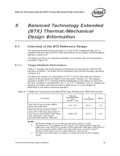
... due to the chassis of across the fan inlet, resulting in Section 6.6. The difference in Ψ ca between the Intel Core™2 Duo processor E8000 series with 6 MB cache, Intel Core™2 Duo processor E7000 series with 3 MB cache, Intel Pentium® dual-core processor E6000, E5000 series with 2 MB cache, and Intel® Celeron® processor E3000 series is provided in the die...
... due to the chassis of across the fan inlet, resulting in Section 6.6. The difference in Ψ ca between the Intel Core™2 Duo processor E8000 series with 6 MB cache, Intel Core™2 Duo processor E7000 series with 3 MB cache, Intel Pentium® dual-core processor E6000, E5000 series with 2 MB cache, and Intel® Celeron® processor E3000 series is provided in the die...