
Data Sheet
Page 8
... Software Developer's Manuals for Core to Bus ratio TDP VCC VSS Intel Core 2 Duo processors and Intel Core 2 Extreme processors support the N/2 feature that allows having more detailed information. 64-bit memory extensions to the IA-32 architecture. In the case of signals where...Front Side Bus (FSB) AGTL+ Storage Conditions Processor Core Execute Disable Bit Intel® 64 Technology Definition A "#" symbol after a signal name refers to an active low signal, indicating a signal is in non-executable memory the processor raises an error to the operating system. For example, when...
... Software Developer's Manuals for Core to Bus ratio TDP VCC VSS Intel Core 2 Duo processors and Intel Core 2 Extreme processors support the N/2 feature that allows having more detailed information. 64-bit memory extensions to the IA-32 architecture. In the case of signals where...Front Side Bus (FSB) AGTL+ Storage Conditions Processor Core Execute Disable Bit Intel® 64 Technology Definition A "#" symbol after a signal name refers to an active low signal, indicating a signal is in non-executable memory the processor raises an error to the operating system. For example, when...
Data Sheet
Page 14
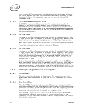
See the Intel® 64 and IA-32 Architectures Software Developer's Manuals, Volume 2A: Instruction Set Reference, A-M and Volume 2B: Instruction Set Reference, N-Z, for the processor. Core C3 .... Before entering C3, the processor core flushes the contents of its architectural states in the C3 state. All of the dual-core processor accesses cacheable memory. Processor behavior in the MWAIT state is also asserted. Except for the caches, the processor core maintains all its cores is asserted, each core returns...
See the Intel® 64 and IA-32 Architectures Software Developer's Manuals, Volume 2A: Instruction Set Reference, A-M and Volume 2B: Instruction Set Reference, N-Z, for the processor. Core C3 .... Before entering C3, the processor core flushes the contents of its architectural states in the C3 state. All of the dual-core processor accesses cacheable memory. Processor behavior in the MWAIT state is also asserted. Except for the caches, the processor core maintains all its cores is asserted, each core returns...

Data Sheet
Page 59
... connect the appropriate pins of 8) Name A[35:3]# A20M# ADS# ADSTB[1:0]# Type Input/ Output Input Input/ Output Input/ Output Description A[35:3]# (Address) define a 236-byte physical memory address space. In sub-phase 2, these signals to accept new bus transactions. Signals Associated Strobe REQ[4:0]#, A[16:3]# ADSTB[0]# A[35:17]# ADSTB[1]# BCLK[1:0] BNR# BPM[2:1]# BPM...
... connect the appropriate pins of 8) Name A[35:3]# A20M# ADS# ADSTB[1:0]# Type Input/ Output Input Input/ Output Input/ Output Description A[35:3]# (Address) define a 236-byte physical memory address space. In sub-phase 2, these signals to accept new bus transactions. Signals Associated Strobe REQ[4:0]#, A[16:3]# ADSTB[0]# A[35:17]# ADSTB[1]# BCLK[1:0] BNR# BPM[2:1]# BPM...

Data Sheet
Page 61
.../ Output Signals Associated Strobe D[15:0]#, DINV[0]# D[31:16]#, DINV[1]# D[47:32]#, DINV[2]# D[63:48]#, DINV[3]# DSTBN[0]# DSTBN[1]# DSTBN[2]# DSTBN[3]# Datasheet 61 Assertion of the addressed memory or input/ output agent. Package Mechanical Specifications and Pin Information Table 12.
.../ Output Signals Associated Strobe D[15:0]#, DINV[0]# D[31:16]#, DINV[1]# D[47:32]#, DINV[2]# D[63:48]#, DINV[3]# DSTBN[0]# DSTBN[1]# DSTBN[2]# DSTBN[3]# Datasheet 61 Assertion of the addressed memory or input/ output agent. Package Mechanical Specifications and Pin Information Table 12.