
Hard Drive Specifications
Page 6
... High Register 68 9.4 Cylinder Low Register 68 9.5 Data Register 68 9.6 Device Control Register 69 9.7 Drive Address Register 69 9.8 Device/Head Register 69 9.9 Error Register 70 9.10 Features Register 71 9.11 Sector Count Register 71 9.12 Sector Number Register 71 9.13 Status Register 71... iv O E M Specifications for DTTA-3xxxxx 6.6.3 Data Reliability 48 6.6.4 Cable Noise Interference 48 6.7 Mechanical ...
... High Register 68 9.4 Cylinder Low Register 68 9.5 Data Register 68 9.6 Device Control Register 69 9.7 Drive Address Register 69 9.8 Device/Head Register 69 9.9 Error Register 70 9.10 Features Register 71 9.11 Sector Count Register 71 9.12 Sector Number Register 71 9.13 Status Register 71... iv O E M Specifications for DTTA-3xxxxx 6.6.3 Data Reliability 48 6.6.4 Cable Noise Interference 48 6.7 Mechanical ...

Hard Drive Specifications
Page 7
... Addressing Mode 76 10.3.2 LBA Addressing Mode 76 10.4 Overlapped and Queued Feature 76 10.5 Power Management Feature 77 10.5.1 Power Mode 78 10.5.2 Power Management Commands 78 10.5.3 Standby timer 78 10.5.4 Interface Capability for operation (In LBA mode 86 10.9 Write Cache Function 87 10.10 Reassign Function 87 10.10.1 Auto Reassign Function 88 10.11 Automatic Drive Maintenance (ADM 88...
... Addressing Mode 76 10.3.2 LBA Addressing Mode 76 10.4 Overlapped and Queued Feature 76 10.5 Power Management Feature 77 10.5.1 Power Mode 78 10.5.2 Power Management Commands 78 10.5.3 Standby timer 78 10.5.4 Interface Capability for operation (In LBA mode 86 10.9 Write Cache Function 87 10.10 Reassign Function 87 10.10.1 Auto Reassign Function 88 10.11 Automatic Drive Maintenance (ADM 88...

Hard Drive Specifications
Page 9
... describes the specifications of the following IBM 3.5-inch, ATA interface hard disk drives: DTTA-351680 ( 16.8 GB ) ( 5400 rpm ) | DTTA-351350 ( 13.5 GB ) ( 5400 rpm ) DTTA-351290 ( 12.9 GB ) ( 5400 rpm ) DTTA-351010 ( 10.1 GB ) DTTA-350840 ( 8.4 GB ) DTTA-350640 ( 6.4 GB ) DTTA-350430 ( 4.3 GB ) DTTA-350320 ( 3.2 GB ) ( 5400 rpm ) ( 5400 rpm ) ( 5400 rpm ) ( 5400 rpm ) ( 5400 rpm ) DTTA-371440 ( 14.4 GB ) ( 7200 rpm ) DTTA-371290 ( 12.9 GB ) ( 7200 rpm ) DTTA-371010 ( 10.1 GB ) ( 7200 rpm ) Note: The specifications...
... describes the specifications of the following IBM 3.5-inch, ATA interface hard disk drives: DTTA-351680 ( 16.8 GB ) ( 5400 rpm ) | DTTA-351350 ( 13.5 GB ) ( 5400 rpm ) DTTA-351290 ( 12.9 GB ) ( 5400 rpm ) DTTA-351010 ( 10.1 GB ) DTTA-350840 ( 8.4 GB ) DTTA-350640 ( 6.4 GB ) DTTA-350430 ( 4.3 GB ) DTTA-350320 ( 3.2 GB ) ( 5400 rpm ) ( 5400 rpm ) ( 5400 rpm ) ( 5400 rpm ) ( 5400 rpm ) DTTA-371440 ( 14.4 GB ) ( 7200 rpm ) DTTA-371290 ( 12.9 GB ) ( 7200 rpm ) DTTA-371010 ( 10.1 GB ) ( 7200 rpm ) Note: The specifications...

Hard Drive Specifications
Page 15
... IBM Corp. 1998 7 The default value of the above list indicate Ship Default. Default Drive Parameters Model Capacity Word 1 Word 3 Word 6 (GB) (Cyl) (Head) (Sect/Trk) DTTA-351680 16.9 16383 16* 63 15 | DTTA-351350 13.5 16383 16* 63 | 15 DTTA-351290 12.9 16383 16* 63 15 DTTA-351010 10.1 16383 16* 63 15 DTTA-350840 8.4 16383 16* 63 15 DTTA...
... IBM Corp. 1998 7 The default value of the above list indicate Ship Default. Default Drive Parameters Model Capacity Word 1 Word 3 Word 6 (GB) (Cyl) (Head) (Sect/Trk) DTTA-351680 16.9 16383 16* 63 15 | DTTA-351350 13.5 16383 16* 63 | 15 DTTA-351290 12.9 16383 16* 63 15 DTTA-351010 10.1 16383 16* 63 15 DTTA-350840 8.4 16383 16* 63 15 DTTA...

Hard Drive Specifications
Page 16
...111.6 - 175.6 16.6 (PIO Mode-4) 33.3 (Ultra DMA/33) 464 7200 4.17 178.1 max 13,700 2.440 max 8 5/5/4 10/9/7 Embeded Sector Servo 8 OEM Specifications for DTTA-3xxxxx 3.2 Data Sheet Media Transfer Rate (Mb/sec) Interface Transfer Rate (MB/sec) Data Buffer Size (KB) Rotational Speed (RPM) Average ...Latency (msec) Recording Density (Kbpi) Track Density (TPI) Areal Density (Gb/sq.in.) Number of Zone Number of Data...
...111.6 - 175.6 16.6 (PIO Mode-4) 33.3 (Ultra DMA/33) 464 7200 4.17 178.1 max 13,700 2.440 max 8 5/5/4 10/9/7 Embeded Sector Servo 8 OEM Specifications for DTTA-3xxxxx 3.2 Data Sheet Media Transfer Rate (Mb/sec) Interface Transfer Rate (MB/sec) Data Buffer Size (KB) Rotational Speed (RPM) Average ...Latency (msec) Recording Density (Kbpi) Track Density (TPI) Areal Density (Gb/sq.in.) Number of Zone Number of Data...

Hard Drive Specifications
Page 17
...: The above parameters contribute to the performance of the actual system. Mechanical Positioning Performance Typical 8.5 msec 9.5 msec Max 9.5 msec 10.5 msec "Typical" and "Max" are other parameters that contribute to file performance. Drive Characteristics 9 There are given throughout the performance specification by a host to DRQ) Seek (from the command is written into...
...: The above parameters contribute to the performance of the actual system. Mechanical Positioning Performance Typical 8.5 msec 9.5 msec Max 9.5 msec 10.5 msec "Typical" and "Max" are other parameters that contribute to file performance. Drive Characteristics 9 There are given throughout the performance specification by a host to DRQ) Seek (from the command is written into...

Hard Drive Specifications
Page 18
...drive over the full range of the environmental and voltage conditions. (See section on page 13. 10 OEM Specifications for arrival problems. The Average Seek Time is measured as the weighted average of all possible seek combinations. The measurement method is not employed to correct for DTTA... a reliable read or write implies that error correction/recovery is given in 3.3.5, "Throughput" on Environment and D.C. Head Switch Time DTTA-35xxxx 2.0 msec DTTA-37xxxx 1.8 msec A head switch time is measured from both directions (inward and outward). 3.3.2.3 Head Switch Time (Head Skew) ...
...drive over the full range of the environmental and voltage conditions. (See section on page 13. 10 OEM Specifications for arrival problems. The Average Seek Time is measured as the weighted average of all possible seek combinations. The measurement method is not employed to correct for DTTA... a reliable read or write implies that error correction/recovery is given in 3.3.5, "Throughput" on Environment and D.C. Head Switch Time DTTA-35xxxx 2.0 msec DTTA-37xxxx 1.8 msec A head switch time is measured from both directions (inward and outward). 3.3.2.3 Head Switch Time (Head Skew) ...

Hard Drive Specifications
Page 19
...includes the time required for a revolution 11.1 msec 8.3 msec Average Latency 5.56 msec 4.17 msec DTTA-35xxxx DTTA-37xxxx Power On to perform a media access command (e.g. Latency Time 3.3.3 Drive Ready Time Time for the internal self diagnostics. The measurement method is defined as the average of ... disk to complete seek the next sequential block after reading the last track in which the drive is able to Ready Figure 10. 3.3.2.4 Cylinder Switch Time (Cylinder Skew) Cylinder Switch Time (Typical) Figure 7. Drive Ready Time 13 sec (typical) / 31 sec (max) 18 sec (typical) / ...
...includes the time required for a revolution 11.1 msec 8.3 msec Average Latency 5.56 msec 4.17 msec DTTA-35xxxx DTTA-37xxxx Power On to perform a media access command (e.g. Latency Time 3.3.3 Drive Ready Time Time for the internal self diagnostics. The measurement method is defined as the average of ... disk to complete seek the next sequential block after reading the last track in which the drive is able to Ready Figure 10. 3.3.2.4 Cylinder Switch Time (Cylinder Skew) Cylinder Switch Time (Typical) Figure 7. Drive Ready Time 13 sec (typical) / 31 sec (max) 18 sec (typical) / ...

Hard Drive Specifications
Page 20
... (Mbyte/sec) defines the maximum data transfer rate on AT Bus. Data Transfer Speed DTTA-35xxxx 15.2 Mbyte/sec 12 Mbyte/sec 8.3 Mbyte/sec 6 Mbyte/sec 33.3 Mbyte/sec DTTA-37xxxx 16.2 Mbyte/sec 13 Mbyte/sec 10.1 Mbyte/sec 8 Mbyte/sec 33.3 Mbyte/sec Instantaneous Disk-Buffer Transfer Rate (Mbyte/...host. It is given in 3.3.5, "Throughput" on the speed of the linear density recording. It also depends on page 13. 12 OEM Specifications for DTTA-3xxxxx typical Disk-Buffer Transfer (Zone 7) Instantaneous - The measurement method is derived by considering head/cylinder change time.
... (Mbyte/sec) defines the maximum data transfer rate on AT Bus. Data Transfer Speed DTTA-35xxxx 15.2 Mbyte/sec 12 Mbyte/sec 8.3 Mbyte/sec 6 Mbyte/sec 33.3 Mbyte/sec DTTA-37xxxx 16.2 Mbyte/sec 13 Mbyte/sec 10.1 Mbyte/sec 8 Mbyte/sec 33.3 Mbyte/sec Instantaneous Disk-Buffer Transfer Rate (Mbyte/...host. It is given in 3.3.5, "Throughput" on the speed of the linear density recording. It also depends on page 13. 12 OEM Specifications for DTTA-3xxxxx typical Disk-Buffer Transfer (Zone 7) Instantaneous - The measurement method is derived by considering head/cylinder change time.
Hard Drive Specifications
Page 22
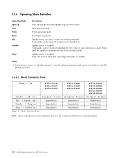
... mode Read operation mode Spindle motor and servo system are working normally. Only soft reset or hard reset can be received immediately, but write or read operations cannot begin until the spindle is ...) Sleep - - > Standby (sec) Figure 13. Mode Transition Time DTTA-371440 DTTA-371290 DTTA-371010 14 (typical) / 31 (max) Immediately Immediately Immediately DTTA-351680 DTTA-351350 DTTA-351290 12 (typical) / 31 (max) Immediately Immediately Immediately DTTA-351010 DTTA-350840 DTTA-350640 DTTA-350430 DTTA-350320 10 (typical) / 31 (max) Immediately Immediately Immediately Note: The actual spin...
... mode Read operation mode Spindle motor and servo system are working normally. Only soft reset or hard reset can be received immediately, but write or read operations cannot begin until the spindle is ...) Sleep - - > Standby (sec) Figure 13. Mode Transition Time DTTA-371440 DTTA-371290 DTTA-371010 14 (typical) / 31 (max) Immediately Immediately Immediately DTTA-351680 DTTA-351350 DTTA-351290 12 (typical) / 31 (max) Immediately Immediately Immediately DTTA-351010 DTTA-350840 DTTA-350640 DTTA-350430 DTTA-350320 10 (typical) / 31 (max) Immediately Immediately Immediately Note: The actual spin...

Hard Drive Specifications
Page 28
...Drive. 2. "I /O" designates an input/output common. 4. The signal lines marked with (*) are listed as follows: PIN SIGNAL I/O Type PIN SIGNAL I/O Type 01 RESET I TTL 02 GND 03 DD07 I/O 3 state 04 DD08 I/O 3 state 05 DD06 I/O 3 state 06 DD09 I/O 3 state 07 DD05 I/O 3 state 08 DD10 I/O 3 state 09 DD04 I/O 3 state 10... I TTL 39 DASP I/O OC 40 GND Figure 15. These lines revert back to the Drive. 3. Write Operation Read Operation Special Definition (for DTTA-3xxxxx "OC" designates Open-Collector or Open-Drain output. 5. 6.1.2 Signal Definition The pin assignments of ...
...Drive. 2. "I /O" designates an input/output common. 4. The signal lines marked with (*) are listed as follows: PIN SIGNAL I/O Type PIN SIGNAL I/O Type 01 RESET I TTL 02 GND 03 DD07 I/O 3 state 04 DD08 I/O 3 state 05 DD06 I/O 3 state 06 DD09 I/O 3 state 07 DD05 I/O 3 state 08 DD10 I/O 3 state 09 DD04 I/O 3 state 10... I TTL 39 DASP I/O OC 40 GND Figure 15. These lines revert back to the Drive. 3. Write Operation Read Operation Special Definition (for DTTA-3xxxxx "OC" designates Open-Collector or Open-Drain output. 5. 6.1.2 Signal Definition The pin assignments of ...

Hard Drive Specifications
Page 30
... an open then the device address is used only for Ultra D M A data transfers between host and drive. -DDMARDY is controlled by mistake. This signal is held asserted by the host before data is ready to... ) . If CSEL is grounded then the device address is -50% to 5Volt through 10 kΩ resistor. -HDMARDY (Ultra DMA) This signal is used only for Ultra D M A data transfers between host and drive, shall be used for an Ultra D M A data out transfer. This signal is ...the host for DMA data transfers between host and drive. -HDMARDY is a flow control signal for DTTA-3xxxxx
... an open then the device address is used only for Ultra D M A data transfers between host and drive. -DDMARDY is controlled by mistake. This signal is held asserted by the host before data is ready to... ) . If CSEL is grounded then the device address is -50% to 5Volt through 10 kΩ resistor. -HDMARDY (Ultra DMA) This signal is used only for Ultra D M A data transfers between host and drive, shall be used for an Ultra D M A data out transfer. This signal is ...the host for DMA data transfers between host and drive. -HDMARDY is a flow control signal for DTTA-3xxxxx

Hard Drive Specifications
Page 33
PIO cycle timings Notes: 1. Apply to +IORDY low T11 +IORDY pulse width MIN MAX Note (nsec) (nsec) 120 25 70 25 20 10 20 5 40 1 30 1 10 35 1250 Figure 18. CS0, CS1 +DA0 2 DIOR, DIOW < T1 > < < < T9 > T0 > T2 > < T2I > Write data +DD00 15 < T3 > < T4 > Read data +DD00 15 HIOCS16 > ...
PIO cycle timings Notes: 1. Apply to +IORDY low T11 +IORDY pulse width MIN MAX Note (nsec) (nsec) 120 25 70 25 20 10 20 5 40 1 30 1 10 35 1250 Figure 18. CS0, CS1 +DA0 2 DIOR, DIOW < T1 > < < < T9 > T0 > T2 > < T2I > Write data +DD00 15 < T3 > < T4 > Read data +DD00 15 HIOCS16 > ...

Hard Drive Specifications
Page 36
... pulse width TL HIOR/ HIOW to DMARQ delay TZ DMACK to tristate Figure 20. Multiword D M A cycle timings [nsec] MIN MAX Note 120 70 20 5 20 10 0 5 25 35 25 28 OEM Specifications for...
... pulse width TL HIOR/ HIOW to DMARQ delay TZ DMACK to tristate Figure 20. Multiword D M A cycle timings [nsec] MIN MAX Note 120 70 20 5 20 10 0 5 25 35 25 28 OEM Specifications for...

Hard Drive Specifications
Page 37
... MIN MAX MIN MAX MIN MAX 0 0 0 20 20 20 20 70 20 70 20 70 0 0 0 0 230 0 200 0 170 114 75 55 235 156 117 10 10 10 0 0 0 70 48 34 6 6 6 Specification 29 a Proposal for a New Protocol in ATA/ATAPI-4 (X3T13/1153D Revision 16) 6.2.4.1 Initiating Read DMA DMARQ DMACK STOP HDMARDY... Tui Tack Tenv Tzrdy Tfs Tcyc T2cyc Taz Tzad Tdvs Tdvh Unlimited interlock time Setup time before DMACK assertion Envelope time Wait time before driving DSTROBE First strobe time Cycle Time 2 Cycle time Output release time Output enable time Data setup time (at device side) Data Hold time...
... MIN MAX MIN MAX MIN MAX 0 0 0 20 20 20 20 70 20 70 20 70 0 0 0 0 230 0 200 0 170 114 75 55 235 156 117 10 10 10 0 0 0 70 48 34 6 6 6 Specification 29 a Proposal for a New Protocol in ATA/ATAPI-4 (X3T13/1153D Revision 16) 6.2.4.1 Initiating Read DMA DMARQ DMACK STOP HDMARDY... Tui Tack Tenv Tzrdy Tfs Tcyc T2cyc Taz Tzad Tdvs Tdvh Unlimited interlock time Setup time before DMACK assertion Envelope time Wait time before driving DSTROBE First strobe time Cycle Time 2 Cycle time Output release time Output enable time Data setup time (at device side) Data Hold time...

Hard Drive Specifications
Page 39
... < Tli > < Tmli > < Trp > < Tack > < Tack > < Trfs > < Tli > < > Trdyz Taz < > Tds < > < > Tdh XXX RD Data XXXXXXXXXXXXXXXXXX XXX CRC XXXXXXXXXX Device drives DB >< Host drives DB PARAMETER DESCRIPTION Trfs Trp Tli Taz Tzah Tmli Tds Tdh Tack Trdyz Ready to final strobe time Ready to pause time Limited interlock... [nsec] MODE0 MODE1 MODE2 MIN MAX MIN MAX MIN MAX 75 60 50 160 125 100 0 150 0 150 0 150 10 10 10 20 20 20 20 20 20 15 10 7 5 5 5 20 20 20 20 20 20 Figure 23. Ultra D M A cycle timings (Host terminating Read) Specification 31
... < Tli > < Tmli > < Trp > < Tack > < Tack > < Trfs > < Tli > < > Trdyz Taz < > Tds < > < > Tdh XXX RD Data XXXXXXXXXXXXXXXXXX XXX CRC XXXXXXXXXX Device drives DB >< Host drives DB PARAMETER DESCRIPTION Trfs Trp Tli Taz Tzah Tmli Tds Tdh Tack Trdyz Ready to final strobe time Ready to pause time Limited interlock... [nsec] MODE0 MODE1 MODE2 MIN MAX MIN MAX MIN MAX 75 60 50 160 125 100 0 150 0 150 0 150 10 10 10 20 20 20 20 20 20 15 10 7 5 5 5 20 20 20 20 20 20 Figure 23. Ultra D M A cycle timings (Host terminating Read) Specification 31

Hard Drive Specifications
Page 40
...(Device terminating Read) 32 OEM Specifications for DTTA-3xxxxx 6.2.4.4 Device Terminating Read DMA < > Tss DMARQ < Tmli > DMACK < Tli > < Tack > STOP < Tli > < Tack > HDMARDY < Tli > < > Trdyz DSTROBE < > Taz Tds < > < > Tdh DB(15:00) XXXXX XXXXXXXXXXXXXXXXXXXXXX CRC XXXXXXXXXX < Tzah > > < Device drives DB Host drives DB PARAMETER DESCRIPTION Tss Tli Taz Tzah Tmli ... negation Pull up time before DSTROBE release [nsec] MODE0 MODE1 MODE2 MIN MAX MIN MAX MIN MAX 50 0 150 10 20 20 15 5 20 20 50 0 150 10 20 20 10 5 20 20 50 0 150 10 20 20 7 5 20 20 Figure 24.
...(Device terminating Read) 32 OEM Specifications for DTTA-3xxxxx 6.2.4.4 Device Terminating Read DMA < > Tss DMARQ < Tmli > DMACK < Tli > < Tack > STOP < Tli > < Tack > HDMARDY < Tli > < > Trdyz DSTROBE < > Taz Tds < > < > Tdh DB(15:00) XXXXX XXXXXXXXXXXXXXXXXXXXXX CRC XXXXXXXXXX < Tzah > > < Device drives DB Host drives DB PARAMETER DESCRIPTION Tss Tli Taz Tzah Tmli ... negation Pull up time before DSTROBE release [nsec] MODE0 MODE1 MODE2 MIN MAX MIN MAX MIN MAX 50 0 150 10 20 20 15 5 20 20 50 0 150 10 20 20 10 5 20 20 50 0 150 10 20 20 7 5 20 20 Figure 24.

Hard Drive Specifications
Page 43
...DMARQ DMACK STOP DDMARDY HSTROBE DB(15:00) < < XXX < Trp > < Tmli > < Tack > < > Trdyz Trfs > < Tli > < Tack > WT Data Tds < > < > Tdh XXXXXXXXXXXXXXXXXXXXXXXXX CRC XXXXXXXXXX Host drives DB > PARAMETER DESCRIPTION Trfs Trp Tli Tmli Tds Tdh Tack Trdyz Ready to final strobe time Ready to pause time Limited interlock time Interlock time... [nsec] MODE0 MODE1 MODE2 MIN MAX MIN MAX MIN MAX 75 60 50 160 125 100 0 150 0 150 0 150 20 20 20 15 10 7 5 5 5 20 20 20 20 20 20 Figure 27. Ultra D M A cycle timings (Device terminating Write) Specification 35
...DMARQ DMACK STOP DDMARDY HSTROBE DB(15:00) < < XXX < Trp > < Tmli > < Tack > < > Trdyz Trfs > < Tli > < Tack > WT Data Tds < > < > Tdh XXXXXXXXXXXXXXXXXXXXXXXXX CRC XXXXXXXXXX Host drives DB > PARAMETER DESCRIPTION Trfs Trp Tli Tmli Tds Tdh Tack Trdyz Ready to final strobe time Ready to pause time Limited interlock time Interlock time... [nsec] MODE0 MODE1 MODE2 MIN MAX MIN MAX MIN MAX 75 60 50 160 125 100 0 150 0 150 0 150 20 20 20 15 10 7 5 5 5 20 20 20 20 20 20 Figure 27. Ultra D M A cycle timings (Device terminating Write) Specification 35

Hard Drive Specifications
Page 44
Ultra D M A cycle timings (Host terminating Write) 36 OEM Specifications for DTTA-3xxxxx 6.2.4.8 Host Terminating Write DMA DMARQ DMACK STOP DDMARDY HSTROBE DB(15:00) < Tli > < Tmli > < > Tss < Tack > < Tli > < > Trdyz < Tli > < Tack > Tds < > < > Tdh XXXXXXXXXXXXXXXXXXXXXXXXXXXXXXXXXXXXXXX CRC XXXXXXXXXX < Host drives DB > PARAMETER DESCRIPTION Tss Tli Tmli Tds Tdh Tack Trdyz Time from strobe to... Pull up time before DSTROBE release [nsec] MODE0 MODE1 MODE2 MIN MAX MIN MAX MIN MAX 50 0 150 20 15 5 20 20 50 0 150 20 10 5 20 20 50 0 150 20 7 5 20 20 Figure 28.
Ultra D M A cycle timings (Host terminating Write) 36 OEM Specifications for DTTA-3xxxxx 6.2.4.8 Host Terminating Write DMA DMARQ DMACK STOP DDMARDY HSTROBE DB(15:00) < Tli > < Tmli > < > Tss < Tack > < Tli > < > Trdyz < Tli > < Tack > Tds < > < > Tdh XXXXXXXXXXXXXXXXXXXXXXXXXXXXXXXXXXXXXXX CRC XXXXXXXXXX < Host drives DB > PARAMETER DESCRIPTION Tss Tli Tmli Tds Tdh Tack Trdyz Time from strobe to... Pull up time before DSTROBE release [nsec] MODE0 MODE1 MODE2 MIN MAX MIN MAX MIN MAX 50 0 150 20 15 5 20 20 50 0 150 20 10 5 20 20 50 0 150 20 7 5 20 20 Figure 28.

Hard Drive Specifications
Page 52
...0.9 44 OEM Specifications for DTTA-3xxxxx The following voltage specification is not allowed). Power Supply Current of the drive. 6.5 DC Power Requirements ...Connection to -peak) 0.25 0.04 Seek peak 0.55 0.02 Seek average (*1) 0.33 0.02 Start up (max) 0.7 0.02 RND R/W peak 0.8 0.15 R N D R/W average (*2) 0.42 0.15 Standby/Sleep average 0.165 0.01 +12Volts Pop Mean Std.Dev 0.45 0.1 0.7 0.15 1.7 0.2 0.7 0.1 2 0.1 0.75 0.1 0.65 0.1 0.0045 0.001 Total (W) 6.9 10.1 9.9 0.9 Figure 38. Power Supply Current of DTTA...
...0.9 44 OEM Specifications for DTTA-3xxxxx The following voltage specification is not allowed). Power Supply Current of the drive. 6.5 DC Power Requirements ...Connection to -peak) 0.25 0.04 Seek peak 0.55 0.02 Seek average (*1) 0.33 0.02 Start up (max) 0.7 0.02 RND R/W peak 0.8 0.15 R N D R/W average (*2) 0.42 0.15 Standby/Sleep average 0.165 0.01 +12Volts Pop Mean Std.Dev 0.45 0.1 0.7 0.15 1.7 0.2 0.7 0.1 2 0.1 0.75 0.1 0.65 0.1 0.0045 0.001 Total (W) 6.9 10.1 9.9 0.9 Figure 38. Power Supply Current of DTTA...