Hardware Maintenance Manual
Page 5
... 71 © Copyright IBM Corp. 2001 Front bezel Types 8307, 8308, 8310, 8311, 8314, and 8315 72 Replacing a microprocessor 72 Hard disk drive removal 73 Types 8303, 8304, and 8312 73 Types 8305, 8306, 8309, and 8313 74 Types 8307, 8308, 8310, 8311, 8314, and 8315 . . 77 Power supply removal 77 Types 8301... and 8302 77 Types 8303, 8304, and 8312 78 Types 8305, 8306, 8309, and 8313 79 Types 8307, 8308, 8310, 8311, 8314, and 8315 . . 80 System board...
... 71 © Copyright IBM Corp. 2001 Front bezel Types 8307, 8308, 8310, 8311, 8314, and 8315 72 Replacing a microprocessor 72 Hard disk drive removal 73 Types 8303, 8304, and 8312 73 Types 8305, 8306, 8309, and 8313 74 Types 8307, 8308, 8310, 8311, 8314, and 8315 . . 77 Power supply removal 77 Types 8301... and 8302 77 Types 8303, 8304, and 8312 78 Types 8305, 8306, 8309, and 8313 79 Types 8307, 8308, 8310, 8311, 8314, and 8315 . . 80 System board...
Hardware Maintenance Manual
Page 12
...IBM Setup Utility program, this feature is called Serial Port Ring Detect for an external modem and Modem Ring Detect for an internal modem) v Remote Administration v Automatic power-on startup v System Management (SM) BIOS and SM software v Ability to support built-in , line out, and microphone) Expansion Two drive bays Power v 125 W power supply... with manual voltage selection switch v Automatic 50/60 Hz input frequency switching v Advanced Power Management support v Advanced Configuration and Power Interface (ACPI) support Security...
...IBM Setup Utility program, this feature is called Serial Port Ring Detect for an external modem and Modem Ring Detect for an internal modem) v Remote Administration v Automatic power-on startup v System Management (SM) BIOS and SM software v Ability to support built-in , line out, and microphone) Expansion Two drive bays Power v 125 W power supply... with manual voltage selection switch v Automatic 50/60 Hz input frequency switching v Advanced Power Management support v Advanced Configuration and Power Interface (ACPI) support Security...

Hardware Maintenance Manual
Page 14
... Remote Program Load (RPL) and Dynamic Host Configuration Protocol (DHCP) v Wake on LAN v Wake on Ring (in the IBM Setup Utility program, this feature is called Serial Port Ring Detect for an external modem and Modem Ring Detect for an internal ...accelerated graphics port (AGP) expansion slot (supports low-profile adapters only) Power v 160 W power supply with manual voltage selection switch v Automatic 50/60 Hz input frequency switching v Advanced Power Management support v Advanced Configuration and Power Interface (ACPI) support Security features v User and administrator passwords v Support...
... Remote Program Load (RPL) and Dynamic Host Configuration Protocol (DHCP) v Wake on LAN v Wake on Ring (in the IBM Setup Utility program, this feature is called Serial Port Ring Detect for an external modem and Modem Ring Detect for an internal ...accelerated graphics port (AGP) expansion slot (supports low-profile adapters only) Power v 160 W power supply with manual voltage selection switch v Automatic 50/60 Hz input frequency switching v Advanced Power Management support v Advanced Configuration and Power Interface (ACPI) support Security features v User and administrator passwords v Support...
Hardware Maintenance Manual
Page 16
... Remote Program Load (RPL) and Dynamic Host Configuration Protocol (DHCP) v Wake on LAN v Wake on Ring (in the IBM Setup Utility program, this feature is called Serial Port Ring Detect for an external modem and Modem Ring Detect for an internal ... (PCI) adapter slots v One accelerated graphics port (AGP) expansion slot Power v 185 W power supply with manual voltage selection switch v Automatic 50/60 Hz input frequency switching v Advanced Power Management support v Advanced Configuration and Power Interface (ACPI) support Security features v User and administrator passwords v Support ...
... Remote Program Load (RPL) and Dynamic Host Configuration Protocol (DHCP) v Wake on LAN v Wake on Ring (in the IBM Setup Utility program, this feature is called Serial Port Ring Detect for an external modem and Modem Ring Detect for an internal ... (PCI) adapter slots v One accelerated graphics port (AGP) expansion slot Power v 185 W power supply with manual voltage selection switch v Automatic 50/60 Hz input frequency switching v Advanced Power Management support v Advanced Configuration and Power Interface (ACPI) support Security features v User and administrator passwords v Support ...
Hardware Maintenance Manual
Page 18
...v Remote Program Load (RPL) and Dynamic Host Configuration Protocol (DHCP) v Wake on LAN v Wake on Ring (in the IBM Setup Utility program, this feature is called Serial Port Ring Detect for an external modem and Modem Ring Detect for an internal modem... (PCI) adapter slots v One accelerated graphics port (AGP) expansion slot Power v 185 W power supply with manual voltage selection switch v Automatic 50/60 Hz input frequency switching v Advanced Power Management support v Advanced Configuration and Power Interface (ACPI) support Security features v User and administrator passwords v Support ...
...v Remote Program Load (RPL) and Dynamic Host Configuration Protocol (DHCP) v Wake on LAN v Wake on Ring (in the IBM Setup Utility program, this feature is called Serial Port Ring Detect for an external modem and Modem Ring Detect for an internal modem... (PCI) adapter slots v One accelerated graphics port (AGP) expansion slot Power v 185 W power supply with manual voltage selection switch v Automatic 50/60 Hz input frequency switching v Advanced Power Management support v Advanced Configuration and Power Interface (ACPI) support Security features v User and administrator passwords v Support ...

Hardware Maintenance Manual
Page 48
Locating components Types 8303, 8304, and 8312 The following illustration will help you locate the various components in your computer. 1 Power supply 2 PCI slot 3 AGP slot (some models) 4 Support bar 5 DIMM 6 Hard disk drive 7 CD-ROM drive or DVD-ROM drive 8 Diskette drive 42 Hardware Maintenance Manual
Locating components Types 8303, 8304, and 8312 The following illustration will help you locate the various components in your computer. 1 Power supply 2 PCI slot 3 AGP slot (some models) 4 Support bar 5 DIMM 6 Hard disk drive 7 CD-ROM drive or DVD-ROM drive 8 Diskette drive 42 Hardware Maintenance Manual
Hardware Maintenance Manual
Page 50
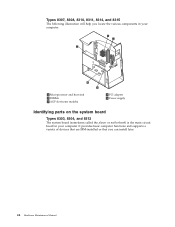
Types 8307, 8308, 8310, 8311, 8314, and 8315 The following illustration will help you can install later. 44 Hardware Maintenance Manual It provides basic computer functions and supports a variety of devices that are IBM-installed or that you locate the various components in your computer. 1 Microprocessor and heat sink 2 DIMMs 3 AGP slot (some models) 4 PCI adapter 5 Power supply Identifying parts on the system board Types 8303, 8304, and 8312 The system board (sometimes called the planar or motherboard) is the main circuit board in your computer.
Types 8307, 8308, 8310, 8311, 8314, and 8315 The following illustration will help you can install later. 44 Hardware Maintenance Manual It provides basic computer functions and supports a variety of devices that are IBM-installed or that you locate the various components in your computer. 1 Microprocessor and heat sink 2 DIMMs 3 AGP slot (some models) 4 PCI adapter 5 Power supply Identifying parts on the system board Types 8303, 8304, and 8312 The system board (sometimes called the planar or motherboard) is the main circuit board in your computer.

Hardware Maintenance Manual
Page 60
... the new drive. Connect one of the slots and gently prying it is set correctly as shown, until it loose. 4. a four-wire power cable that connects to the power supply, and a signal cable that connects to the documentation that comes with your CD-ROM drive or DVD-ROM drive for master/slave jumper...
... the new drive. Connect one of the slots and gently prying it is set correctly as shown, until it loose. 4. a four-wire power cable that connects to the power supply, and a signal cable that connects to the documentation that comes with your CD-ROM drive or DVD-ROM drive for master/slave jumper...

Hardware Maintenance Manual
Page 64
... place. 9. Each integrated drive electronics (IDE) drive requires two cables; a four-wire power cable that connects to the system board. position. 6. Align the screw holes and insert the two screws. 8. Make sure the drive that connects to the power supply and a signal cable that you are installing is the first CD drive or...
... place. 9. Each integrated drive electronics (IDE) drive requires two cables; a four-wire power cable that connects to the system board. position. 6. Align the screw holes and insert the two screws. 8. Make sure the drive that connects to the power supply and a signal cable that you are installing is the first CD drive or...

Hardware Maintenance Manual
Page 68
..., and insert the screws that comes with your drive for master/slave jumper information. 6. Refer to the documentation that secure the drive to the power supply and a signal cable that you are installing is an additional CD drive or DVD drive, set correctly as a slave device. v If it ...as a slave device. Each integrated drive electronics (IDE) drive requires two cables; a four-wire power cable that connects to the bay. 7. Make sure the drive that connects 62 Hardware Maintenance Manual Remove the metal shield from the drive bay by...
..., and insert the screws that comes with your drive for master/slave jumper information. 6. Refer to the documentation that secure the drive to the power supply and a signal cable that you are installing is an additional CD drive or DVD drive, set correctly as a slave device. v If it ...as a slave device. Each integrated drive electronics (IDE) drive requires two cables; a four-wire power cable that connects to the bay. 7. Make sure the drive that connects 62 Hardware Maintenance Manual Remove the metal shield from the drive bay by...

Hardware Maintenance Manual
Page 78
... the two captured screws that hold the fansink in place, and pivot them off the computer and peripheral devices and disconnect all external cables and power cords; Remove the rear section of the machine types, do the following : 1. Replacing a microprocessor To replace a microprocessor on page 77. 4. Front ...bezel from the processor, twist the fansink to heat the processor and loosen the thermal grease. 72 Hardware Maintenance Manual See "Power supply removal" on any of the power source. Note: If the thermal grease seal cannot be broken, you may want to start up the system to break ...
... the two captured screws that hold the fansink in place, and pivot them off the computer and peripheral devices and disconnect all external cables and power cords; Remove the rear section of the machine types, do the following : 1. Replacing a microprocessor To replace a microprocessor on page 77. 4. Front ...bezel from the processor, twist the fansink to heat the processor and loosen the thermal grease. 72 Hardware Maintenance Manual See "Power supply removal" on any of the power source. Note: If the thermal grease seal cannot be broken, you may want to start up the system to break ...

Hardware Maintenance Manual
Page 80
... computer has a CD drive or DVD drive, you installed is latched in the up position. 4. a four-wire power cable that connects to the power supply, and a signal cable that connects to remove the signal and power cables from the front bezel. 74 Hardware Maintenance Manual Install the drive into place. Types 8305, 8306, 8309...
... computer has a CD drive or DVD drive, you installed is latched in the up position. 4. a four-wire power cable that connects to the power supply, and a signal cable that connects to remove the signal and power cables from the front bezel. 74 Hardware Maintenance Manual Install the drive into place. Types 8305, 8306, 8309...

Hardware Maintenance Manual
Page 82
... to the hard disk drive and the other connects to connect your drive connection. Your computer has extra power connectors for your new hard disk. 2. a four-wire power cable that connects to the power supply and a signal cable that connects to the new hard disk drive. 5. Locate the procedure below for .... Connect the extra connector in the signal cable to the system board. Remove the two-connector cable from the hard disk drive. 3. Connect a power connector to connect. One end of drive you are different depending on page 45. 4. You will have an audio cable to the drive. 76 ...
... to the hard disk drive and the other connects to connect your drive connection. Your computer has extra power connectors for your new hard disk. 2. a four-wire power cable that connects to the power supply and a signal cable that connects to the new hard disk drive. 5. Locate the procedure below for .... Connect the extra connector in the signal cable to the system board. Remove the two-connector cable from the hard disk drive. 3. Connect a power connector to connect. One end of drive you are different depending on page 45. 4. You will have an audio cable to the drive. 76 ...

Hardware Maintenance Manual
Page 83
...4. Chapter 6. Turn off the server and peripheral devices and disconnect all external cables and power cords; Remove the screws securing the hard disk drive. 4. Power supply removal Types 8301 and 8302 To remove the power supply, do the following : 1. See "Removing the cover Types 8301 and 8302" on ... 2. FRU Removals 77 then, remove the cover. Disconnect all external cables and power cords; Remove the power supply cables from the front left corner of the machine. Remove the screw holding the power source from the front of the box. 3. Turn off the server and peripheral...
...4. Chapter 6. Turn off the server and peripheral devices and disconnect all external cables and power cords; Remove the screws securing the hard disk drive. 4. Power supply removal Types 8301 and 8302 To remove the power supply, do the following : 1. See "Removing the cover Types 8301 and 8302" on ... 2. FRU Removals 77 then, remove the cover. Disconnect all external cables and power cords; Remove the power supply cables from the front left corner of the machine. Remove the screw holding the power source from the front of the box. 3. Turn off the server and peripheral...

Hardware Maintenance Manual
Page 84
Slide the main portion of the power supply. 7. then, remove the cover. See "Types 8303, 8304, and 8312" on page 40. 78 Hardware Maintenance Manual Remove the screw holding the rear portion of the power supply to the left and lift it out. Lift the rear portion of the power source. 6. Turn off the server and peripheral devices and disconnect all external cables and power cords; 5. Types 8303, 8304, and 8312 To remove the power supply, do the following: 1. Remove the hard disk drive guide from the top of the power supply out.
Slide the main portion of the power supply. 7. then, remove the cover. See "Types 8303, 8304, and 8312" on page 40. 78 Hardware Maintenance Manual Remove the screw holding the rear portion of the power supply to the left and lift it out. Lift the rear portion of the power source. 6. Turn off the server and peripheral devices and disconnect all external cables and power cords; 5. Types 8303, 8304, and 8312 To remove the power supply, do the following: 1. Remove the hard disk drive guide from the top of the power supply out.

Hardware Maintenance Manual
Page 85
Slide the power supply forward to . 3. Types 8305, 8306, 8309, and 8313 1. FRU Removals 79 Remove the two screws that hold the power supply in place. 4. Remove the cover. Chapter 6. Disconnect all wires that the power supply is attached to the back of the chassis by a latch on page 40. 2. The power supply is attached to detach if from the chassis. 4. 2. Lift the power supply out. See "Types 8305, 8306, 8309, and 8313" on the front. Remove the four screws that hold the power supply to the base of the chassis. 3. Lift out the power supply.
Slide the power supply forward to . 3. Types 8305, 8306, 8309, and 8313 1. FRU Removals 79 Remove the two screws that hold the power supply in place. 4. Remove the cover. Chapter 6. Disconnect all wires that the power supply is attached to the back of the chassis by a latch on page 40. 2. The power supply is attached to detach if from the chassis. 4. 2. Lift the power supply out. See "Types 8305, 8306, 8309, and 8313" on the front. Remove the four screws that hold the power supply to the base of the chassis. 3. Lift out the power supply.

Hardware Maintenance Manual
Page 86
...the system board. 5. Remove the two screws holding the power supply to the chassis. 80 Hardware Maintenance Manual Lift out the power supply. See "Removing the cover Types 8301 and 8302" on page 41. 2. Remove the power supply. Turn off the server and peripheral devices and disconnect all ...external cables and power cords; then, remove the cover. See "Power supply removal" on page 71. ...
...the system board. 5. Remove the two screws holding the power supply to the chassis. 80 Hardware Maintenance Manual Lift out the power supply. See "Removing the cover Types 8301 and 8302" on page 41. 2. Remove the power supply. Turn off the server and peripheral devices and disconnect all ...external cables and power cords; then, remove the cover. See "Power supply removal" on page 71. ...

Hardware Maintenance Manual
Page 90
b. Route the hard disk drive IDE cable around the power plug on the back of the power supply. 84 Hardware Maintenance Manual Route both the hard disk drive IDE cable and the hard disk drive power cable through the plastic clip attached to the hard disk drive IDE cable as shown. c. a. Route the hard disk drive power cable through the plastic clip shown on the board as shown.
b. Route the hard disk drive IDE cable around the power plug on the back of the power supply. 84 Hardware Maintenance Manual Route both the hard disk drive IDE cable and the hard disk drive power cable through the plastic clip attached to the hard disk drive IDE cable as shown. c. a. Route the hard disk drive power cable through the plastic clip shown on the board as shown.

Hardware Maintenance Manual
Page 93
... format the hard disk drive. Check/Verify Check the following : 1. v Power Cord v On/Off Switch connector v On/Off Switch Power Supply connector v System Board Power Supply connectors v Microprocessor(s) connection Check the power-on switch for proper installation. Always begin with ″General Checkout″ on...on , the power supply fan is corrupted. Attempt to -FRU index lists error symptoms and possible causes. Replace the hard disk drive. Power Supply Errors If the power-on indicator is not on the boot drive. FRU/Action Reseat Power Cord © Copyright IBM Corp. 2001 ...
... format the hard disk drive. Check/Verify Check the following : 1. v Power Cord v On/Off Switch connector v On/Off Switch Power Supply connector v System Board Power Supply connectors v Microprocessor(s) connection Check the power-on switch for proper installation. Always begin with ″General Checkout″ on...on , the power supply fan is corrupted. Attempt to -FRU index lists error symptoms and possible causes. Replace the hard disk drive. Power Supply Errors If the power-on indicator is not on the boot drive. FRU/Action Reseat Power Cord © Copyright IBM Corp. 2001 ...

Hardware Maintenance Manual
Page 105
...in warning statement 4. Go to review the log file 2. No action Chapter 7. Riser card, if installed 3. IDE signal cable 2. Check power supply 3. Re-run test 3. If a component is called out is connected and/or enabled 2. Flash the system and re-test 3. Diagnostic ...function test 1. Symptom-to the ″Undetermined problems″ section 2. Flash the system 3. Go to -FRU Index 99 System board 1. Check power supply 3. System board 1. Go to reset the log file 1. Flash the system and re-test 3. System board 1. Component that is called out,...
...in warning statement 4. Go to review the log file 2. No action Chapter 7. Riser card, if installed 3. IDE signal cable 2. Check power supply 3. Re-run test 3. If a component is called out is connected and/or enabled 2. Flash the system and re-test 3. Diagnostic ...function test 1. Symptom-to the ″Undetermined problems″ section 2. Flash the system 3. Go to -FRU Index 99 System board 1. Check power supply 3. System board 1. Go to reset the log file 1. Flash the system and re-test 3. System board 1. Component that is called out,...

