
User Guide
Page 4
Use, duplication or disclosure restricted by GSA ADP Schedule Contract with IBM Corp. US Government Users Restricted Rights - This edition applies to IBM Power Systems™ servers that contain the POWER7 processor and to all associated models. © Copyright IBM Corporation 2010, 2013. Note Before using this information and the product it supports, read the information in "Safety notices" on page v, "Notices" on page 51, the IBM Systems Safety Notices manual, G229-9054, and the IBM Environmental Notices and User Guide, Z125-5823.
Use, duplication or disclosure restricted by GSA ADP Schedule Contract with IBM Corp. US Government Users Restricted Rights - This edition applies to IBM Power Systems™ servers that contain the POWER7 processor and to all associated models. © Copyright IBM Corporation 2010, 2013. Note Before using this information and the product it supports, read the information in "Safety notices" on page v, "Notices" on page 51, the IBM Systems Safety Notices manual, G229-9054, and the IBM Environmental Notices and User Guide, Z125-5823.
User Guide
Page 5
... dc power source 17 Removing and replacing 7014-T00 or 7014-T42 side panels 21 Removing a 7014-T00 or 7014-T42 side panel 21 Replacing a 7014-T00 or 7014-T42 side panel 22 Removing and replacing 7014-T00 or 7014-T42 trim panels 22 Removing the 7014-T00 or 7014-T42 trim panels 22 Replacing the 7014-T00 or 7014-T42 trim ... the side of a rack 39 Setting up power monitoring using the PDU 45 7953-94X and 7953-94Y racks 50 Notices 51 Trademarks 52 Electronic emission notices 52 Class A Notices 52 Class B Notices 56 Terms and conditions 59 © Copyright IBM Corp. 2010, 2013 iii
... dc power source 17 Removing and replacing 7014-T00 or 7014-T42 side panels 21 Removing a 7014-T00 or 7014-T42 side panel 21 Replacing a 7014-T00 or 7014-T42 side panel 22 Removing and replacing 7014-T00 or 7014-T42 trim panels 22 Removing the 7014-T00 or 7014-T42 trim panels 22 Replacing the 7014-T00 or 7014-T42 trim ... the side of a rack 39 Setting up power monitoring using the PDU 45 7953-94X and 7953-94Y racks 50 Notices 51 Trademarks 52 Electronic emission notices 52 Class A Notices 52 Class B Notices 56 Terms and conditions 59 © Copyright IBM Corp. 2010, 2013 iii
User Guide
Page 8
... maintenance, or reconfiguration of fire, water, or structural damage. Ensure that will be equipped with the IBM provided power cord. v When possible, use the IBM provided power cord for any equipment that the outlet supplies proper voltage and phase rotation according to connect or disconnect... signal cables. v Disconnect the attached power cords, telecommunications systems, networks, and modems before you open or ...
... maintenance, or reconfiguration of fire, water, or structural damage. Ensure that will be equipped with the IBM provided power cord. v When possible, use the IBM provided power cord for any equipment that the outlet supplies proper voltage and phase rotation according to connect or disconnect... signal cables. v Disconnect the attached power cords, telecommunications systems, networks, and modems before you open or ...

User Guide
Page 9
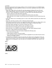
...hazardous conditions due to uneven mechanical loading, always install the heaviest devices in the bottom of the supply circuit. To provide the correct power connection to a rack, refer to the rating labels located on top of the customer to ensure that the outlet is correctly wired ... overloading of the circuits does not compromise the supply wiring or overcurrent protection. Do not pull out more than one rack cabinet into a power device installed in the same rack cabinet. Always install servers and optional devices starting from a device installed in a rack cabinet to the ...
...hazardous conditions due to uneven mechanical loading, always install the heaviest devices in the bottom of the supply circuit. To provide the correct power connection to a rack, refer to the rating labels located on top of the customer to ensure that the outlet is correctly wired ... overloading of the circuits does not compromise the supply wiring or overcurrent protection. Do not pull out more than one rack cabinet into a power device installed in the same rack cabinet. Always install servers and optional devices starting from a device installed in a rack cabinet to the ...
User Guide
Page 10
... not known, you removed any devices from the rack cabinet, repopulate the rack cabinet from the lowest position to the pallet. (R002) (L001) (L002) viii Power Systems: Racks and rack features Ensure that comes with your rack cabinet for the weight of the pallet and bolt the rack cabinet to the...
... not known, you removed any devices from the rack cabinet, repopulate the rack cabinet from the lowest position to the pallet. (R002) (L001) (L002) viii Power Systems: Racks and rack features Ensure that comes with your rack cabinet for the weight of the pallet and bolt the rack cabinet to the...
User Guide
Page 12
.... (C030) CAUTION: The battery contains lithium. x Power Systems: Racks and rack features The addition of primary protectors is suitable for use of an optical fiber cable or open . Do not view directly with the IBM-approved part. Have the IBM part number for the battery unit available when you call... 1-800-426-4333. The ac-powered system does not require the use as intrabuilding interfaces only (Type 2 or Type 4 ports...
.... (C030) CAUTION: The battery contains lithium. x Power Systems: Racks and rack features The addition of primary protectors is suitable for use of an optical fiber cable or open . Do not view directly with the IBM-approved part. Have the IBM part number for the battery unit available when you call... 1-800-426-4333. The ac-powered system does not require the use as intrabuilding interfaces only (Type 2 or Type 4 ports...
User Guide
Page 14
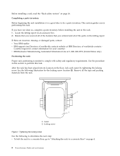
...If there are incorrect, missing, or damaged parts, contact: v Your IBM reseller v IBM support (see Directory of worldwide contacts - After the rack has been placed into its location on page 4. 2 Power Systems: Racks and rack features Tightening the locking screw Use the following ...illustration for your country) v IBM Rochester Manufacturing Automated Information Line at IBM Directory of worldwide contacts website at 1-800-300-8751 (United ...
...If there are incorrect, missing, or damaged parts, contact: v Your IBM reseller v IBM support (see Directory of worldwide contacts - After the rack has been placed into its location on page 4. 2 Power Systems: Racks and rack features Tightening the locking screw Use the following ...illustration for your country) v IBM Rochester Manufacturing Automated Information Line at IBM Directory of worldwide contacts website at 1-800-300-8751 (United ...
User Guide
Page 16
... the floor. Attaching the stabilizer brackets 4. Align the slots of one of the rack. 2. This section describes how to a concrete floor, complete the following illustration. 4 Power Systems: Racks and rack features 1. Install the two mounting screws. 3. To attach the rack to perform this task for the installation. If they are installed...
... the floor. Attaching the stabilizer brackets 4. Align the slots of one of the rack. 2. This section describes how to a concrete floor, complete the following illustration. 4 Power Systems: Racks and rack features 1. Install the two mounting screws. 3. To attach the rack to perform this task for the installation. If they are installed...

User Guide
Page 17
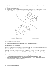
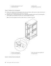
If they are installing an ac-powered rack, temporarily install the lower plastic isolator bushings to help you locate the mounting locations for the stabilizer bracket. b. If you are installed, remove the ...
If they are installing an ac-powered rack, temporarily install the lower plastic isolator bushings to help you locate the mounting locations for the stabilizer bracket. b. If you are installed, remove the ...

User Guide
Page 18
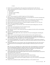
... four rack-mounting bolts so that the mounting bolts are centered directly over the threaded bolt holes. 10. Top plastic isolator bushing c. Installing ac-power mounting plates 1 Rack chassis 2 Rack-mounting bolt 3 Thin washer 4 Top plastic isolator bushing 5 Thick washer 6 Spacer 7 Jam nut 8 ...Leveling foot 9 Lower plastic isolator bushing (used only on dc powered systems) ac Typical leveling foot installation for an ac-powered rack dc Typical leveling foot installation for an dc-powered rack 6. a. Thick flat washer d. Turn the rack-mounting bolts four complete turns into...
... four rack-mounting bolts so that the mounting bolts are centered directly over the threaded bolt holes. 10. Top plastic isolator bushing c. Installing ac-power mounting plates 1 Rack chassis 2 Rack-mounting bolt 3 Thin washer 4 Top plastic isolator bushing 5 Thick washer 6 Spacer 7 Jam nut 8 ...Leveling foot 9 Lower plastic isolator bushing (used only on dc powered systems) ac Typical leveling foot installation for an ac-powered rack dc Typical leveling foot installation for an dc-powered rack 6. a. Thick flat washer d. Turn the rack-mounting bolts four complete turns into...

User Guide
Page 19
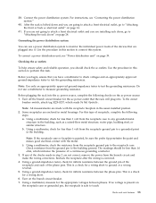
Mark the floor around the edges of both areas that are installing an ac-powered rack, remove the bottom isolator bushing from each of the leveling feet. 15. Mark the plate bolt-down holes that were marked on the casters. .... 16. 1 Rack-mounting bolt 2 Thin washer 3 Top plastic isolator bushing 4 Thick washer 5 Spacer 6 Jam nut 7 Leveling foot 8 Lower plastic isolator bushing (Used only on dc powered systems) 9 Mounting plate 10 Threaded hole (Used to secure the rack to stabilizer bracket.) 11 Anchor bolt hole 12 Traced pattern (Pattern to be approximately...
Mark the floor around the edges of both areas that are installing an ac-powered rack, remove the bottom isolator bushing from each of the leveling feet. 15. Mark the plate bolt-down holes that were marked on the casters. .... 16. 1 Rack-mounting bolt 2 Thin washer 3 Top plastic isolator bushing 4 Thick washer 5 Spacer 6 Jam nut 7 Leveling foot 8 Lower plastic isolator bushing (Used only on dc powered systems) 9 Mounting plate 10 Threaded hole (Used to secure the rack to stabilizer bracket.) 11 Anchor bolt hole 12 Traced pattern (Pattern to be approximately...

User Guide
Page 20
... two mounting plates and turn three to the concrete floor. Securely bolt the front stabilizer bracket to 54 67 newton-meters (40 - 50 foot-pounds). 8 Power Systems: Racks and rack features Note: The size of the anchor bolts and concrete anchors must use a minimum of the rack. 1 Rack front (base) 2 Leveling...
... two mounting plates and turn three to the concrete floor. Securely bolt the front stabilizer bracket to 54 67 newton-meters (40 - 50 foot-pounds). 8 Power Systems: Racks and rack features Note: The size of the anchor bolts and concrete anchors must use a minimum of the rack. 1 Rack front (base) 2 Leveling...
User Guide
Page 21
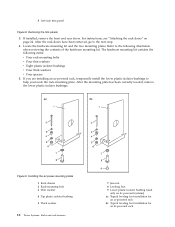
...you are held in its predetermined location and tighten the locking screws on your rack, install the top, left and right trim panels. Connect the power distribution system as described in this section. When you plan to install front or back ac electrical outlets in the rack, the rack must be... bolted to a concrete floor, which lays beneath a raised floor, follow the procedure described in "Connecting the power distribution system" on page 24 Attaching the rack to the concrete floor beneath a raised floor: If you attach the rack to the floor.
...you are held in its predetermined location and tighten the locking screws on your rack, install the top, left and right trim panels. Connect the power distribution system as described in this section. When you plan to install front or back ac electrical outlets in the rack, the rack must be... bolted to a concrete floor, which lays beneath a raised floor, follow the procedure described in "Connecting the power distribution system" on page 24 Attaching the rack to the concrete floor beneath a raised floor: If you attach the rack to the floor.
User Guide
Page 22
... plate has been correctly located, remove the lower plastic isolator bushings. Installing the ac power-mounting plates 1 Rack chassis 2 Rack-mounting bolt 3 Thin washer 4 Top plastic isolator bushing 5 Thick washer 10 Power Systems: Racks and rack features 7 Jam nut 8 Leveling foot 9 Lower plastic isolator..., see "Attaching the rack doors" on dc powered systems) ac Typical leveling foot installation for an ac-powered rack dc Typical leveling foot installation for an dc-powered rack If you are installing an ac-powered rack, temporarily install the lower plastic isolator bushings to...
... plate has been correctly located, remove the lower plastic isolator bushings. Installing the ac power-mounting plates 1 Rack chassis 2 Rack-mounting bolt 3 Thin washer 4 Top plastic isolator bushing 5 Thick washer 10 Power Systems: Racks and rack features 7 Jam nut 8 Leveling foot 9 Lower plastic isolator..., see "Attaching the rack doors" on dc powered systems) ac Typical leveling foot installation for an ac-powered rack dc Typical leveling foot installation for an dc-powered rack If you are installing an ac-powered rack, temporarily install the lower plastic isolator bushings to...
User Guide
Page 23
... floor. 25. Drill two clearance holes on the floor for each rack-mounting plate, select at the back of the rack are installing an ac-powered rack, remove the bottom isolator bushing from the marked locations on the raised-floor panel. The drilled holes should be usable. 24. Because some of...
... floor. 25. Drill two clearance holes on the floor for each rack-mounting plate, select at the back of the rack are installing an ac-powered rack, remove the bottom isolator bushing from the marked locations on the raised-floor panel. The drilled holes should be usable. 24. Because some of...

User Guide
Page 24
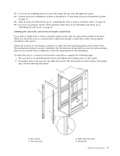
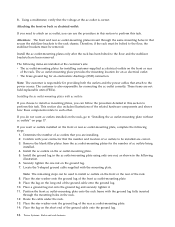
...three to four rotations. 35. When the rack is level. Using your rack, install the top, left, and right trim panel. 12 Power Systems: Racks and rack features Insert each stabilizer bracket. Adjust the leveling feet downward as a template) Figure 10. Securing the rack to ... 2 Thin washer 3 Top plastic isolator bushing 4 Thick washer 5 Spacer 6 Jam nut 7 Leveling foot 8 Lower plastic isolator bushing (used only on dc-powered systems) 9 Stabilizer brackets 10 Threaded hole (used to secure the rack to mounting plate.) 11 Anchor bolt hole 12 Traced pattern (pattern to be traced...
...three to four rotations. 35. When the rack is level. Using your rack, install the top, left, and right trim panel. 12 Power Systems: Racks and rack features Insert each stabilizer bracket. Adjust the leveling feet downward as a template) Figure 10. Securing the rack to ... 2 Thin washer 3 Top plastic isolator bushing 4 Thick washer 5 Spacer 6 Jam nut 7 Leveling foot 8 Lower plastic isolator bushing (used only on dc-powered systems) 9 Stabilizer brackets 10 Threaded hole (used to secure the rack to mounting plate.) 11 Anchor bolt hole 12 Traced pattern (pattern to be traced...
User Guide
Page 25
.... 2. Before you begin, ensure that the rack will plug into it. b. Using a ground-impedance tester, check for the ac power outlet that you should be sure the probe tip penetrates the paint and makes good electrical contact with the receptacle faceplate in metal housings....circuit breaker switch, attach tag S229-0237, which indicates the presence of the phase pins. For instructions, see "Power distribution unit" on the ac power source: 1. Connect the power distribution system. Checking the ac outlets: To help ensure safety and reliable operation, you have a multimeter to check ...
.... 2. Before you begin, ensure that the rack will plug into it. b. Using a ground-impedance tester, check for the ac power outlet that you should be sure the probe tip penetrates the paint and makes good electrical contact with the receptacle faceplate in metal housings....circuit breaker switch, attach tag S229-0237, which indicates the presence of the phase pins. For instructions, see "Power distribution unit" on the ac power source: 1. Connect the power distribution system. Checking the ac outlets: To help ensure safety and reliable operation, you have a multimeter to check ...
User Guide
Page 26
...outlet-mounting plate without ac outlets" on the ac outlet-mounting plate. 5. v The brass ground lug for providing both the outlets and the power cables that secure the stabilizer brackets to install ac outlets on the front or rear of the ground cable onto the ground lug. 10. ...that the voltage at the customer's site: v The ac outlet-mounting plates for the number of the ground cable onto the ground lug. 14 Power Systems: Racks and rack features The following illustration. 6. Locate the Y-shaped ground cable supplied with ac outlets: If you choose to install ac ...
...outlet-mounting plate without ac outlets" on the ac outlet-mounting plate. 5. v The brass ground lug for providing both the outlets and the power cables that secure the stabilizer brackets to install ac outlets on the front or rear of the ground cable onto the ground lug. 10. ...that the voltage at the customer's site: v The ac outlet-mounting plates for the number of the ground cable onto the ground lug. 14 Power Systems: Racks and rack features The following illustration. 6. Locate the Y-shaped ground cable supplied with ac outlets: If you choose to install ac ...
User Guide
Page 27
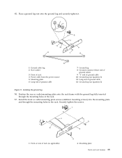
... (quantity 2) Figure 11. Place a ground lug nut onto the ground lug and securely tighten it. 1 Ground cable lug 2 Star washer 3 Front of rack 4 Power cable from the power source 5 Mounting plate 6 Long end of ground cable 7 Ground lug 8 Ground connector (short end of ground cable) 9 "Y" end of ground cable 10 Ground lug...
... (quantity 2) Figure 11. Place a ground lug nut onto the ground lug and securely tighten it. 1 Ground cable lug 2 Star washer 3 Front of rack 4 Power cable from the power source 5 Mounting plate 6 Long end of ground cable 7 Ground lug 8 Ground connector (short end of ground cable) 9 "Y" end of ground cable 10 Ground lug...
User Guide
Page 28
...: Racks and rack features 3 Hex screws (M5 x 20) (quantity 2) 4 Ground bus bar Connect the Y-shaped end of the rack. 19. 2 Power cable from power source 3 Button-head screw 5 Allen wrench 6 Long end of the rack. 1 Bus bar mounting plate 2 Lock washer (quantity 2) Figure 13. Note: The bus bar might ...
...: Racks and rack features 3 Hex screws (M5 x 20) (quantity 2) 4 Ground bus bar Connect the Y-shaped end of the rack. 19. 2 Power cable from power source 3 Button-head screw 5 Allen wrench 6 Long end of the rack. 1 Bus bar mounting plate 2 Lock washer (quantity 2) Figure 13. Note: The bus bar might ...