
User Guide
Page 5
... source 17 Removing and replacing 7014-T00 or 7014-T42 side panels 21 Removing a 7014-T00 or 7014-T42 side panel 21 Replacing a 7014-T00 or 7014-T42 side panel 22 Removing and replacing 7014-T00 or 7014-T42 trim panels 22 Removing the 7014-T00 or 7014-T42 trim panels 22 Replacing the 7014-T00 or 7014-T42 trim panels 23 Attaching the rack doors 24 Attaching a high...
... source 17 Removing and replacing 7014-T00 or 7014-T42 side panels 21 Removing a 7014-T00 or 7014-T42 side panel 21 Replacing a 7014-T00 or 7014-T42 side panel 22 Removing and replacing 7014-T00 or 7014-T42 trim panels 22 Removing the 7014-T00 or 7014-T42 trim panels 22 Replacing the 7014-T00 or 7014-T42 trim panels 23 Attaching the rack doors 24 Attaching a high...
User Guide
Page 7
... information documentation any safety information in product publications to be installed inside or outside of an IT equipment rack. © Copyright IBM Corp. 2010, 2013 v Laser compliance IBM servers may be printed throughout this guide: v DANGER notices call attention to a situation that utilize lasers...in your country, safety information documentation is potentially lethal or extremely hazardous to people. Laser safety information IBM® servers can be obtained by calling the IBM Hotline at 1-800-300-8751. English publication to install, operate, or service this product, you...
... information documentation any safety information in product publications to be installed inside or outside of an IT equipment rack. © Copyright IBM Corp. 2010, 2013 v Laser compliance IBM servers may be printed throughout this guide: v DANGER notices call attention to a situation that utilize lasers...in your country, safety information documentation is potentially lethal or extremely hazardous to people. Laser safety information IBM® servers can be obtained by calling the IBM Hotline at 1-800-300-8751. English publication to install, operate, or service this product, you...
User Guide
Page 8
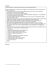
...voltage and phase rotation according to the devices. 3. To Connect: 1. Turn on the devices. (D005) DANGER vi Power Systems: Racks and rack features v The product might be attached to this product during an electrical storm. v Connect any equipment when there is evidence of..., telephone, and communication cables are hazardous. Remove all power cords to properly wired outlets. Ensure that will be equipped with the IBM provided power cord. v Disconnect the attached power cords, telecommunications systems, networks, and modems before you open or service any other product...
...voltage and phase rotation according to the devices. 3. To Connect: 1. Turn on the devices. (D005) DANGER vi Power Systems: Racks and rack features v The product might be attached to this product during an electrical storm. v Connect any equipment when there is evidence of..., telephone, and communication cables are hazardous. Remove all power cords to properly wired outlets. Ensure that will be equipped with the IBM provided power cord. v Disconnect the attached power cords, telecommunications systems, networks, and modems before you open or service any other product...

User Guide
Page 9
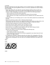
... become unstable if you pull out more than one drawer at a time. v Consideration should be given to the connection of the rack cabinet. The rack might have more than one power cord. v (For fixed drawers.) This drawer is compromised. v Always lower the leveling pads on top... metal parts of the system or the devices that attach to the supply circuit so that overloading of rack-mounted devices. v Do not install a unit in a rack where the internal rack ambient temperatures will exceed the manufacturer's recommended ambient temperature for air flow through the unit. Attempting to ...
... become unstable if you pull out more than one drawer at a time. v Consideration should be given to the connection of the rack cabinet. The rack might have more than one power cord. v (For fixed drawers.) This drawer is compromised. v Always lower the leveling pads on top... metal parts of the system or the devices that attach to the supply circuit so that overloading of rack-mounted devices. v Do not install a unit in a rack where the internal rack ambient temperatures will exceed the manufacturer's recommended ambient temperature for air flow through the unit. Attempting to ...
User Guide
Page 10
... pads are secure. v Ensure that comes with your rack cabinet for the weight of the rack cabinet as you removed any devices from the rack cabinet, repopulate the rack cabinet from the upper positions in the rack cabinet improves rack stability during movement. v If a long-distance relocation is... pads to their highest position. Ensure that all devices in .). v Verify that there are relocating is part of a suite of the loaded rack cabinet. Lower the four leveling pads. - If you received it . Remove all door openings are installed in the new location, complete the ...
... pads are secure. v Ensure that comes with your rack cabinet for the weight of the rack cabinet as you removed any devices from the rack cabinet, repopulate the rack cabinet from the upper positions in the rack cabinet improves rack stability during movement. v If a long-distance relocation is... pads to their highest position. Ensure that all devices in .). v Verify that there are relocating is part of a suite of the loaded rack cabinet. Lower the four leveling pads. - If you received it . Remove all door openings are installed in the new location, complete the ...
User Guide
Page 12
... its wiring. Note: All Ethernet cables must not be metallically connected to the interfaces that connect to OSP wiring. x Power Systems: Racks and rack features Note the following : v Network telecommunications facilities v Locations where the NEC (National Electrical Code) applies The intrabuilding ports of this... do not view directly with optical instruments, and avoid direct exposure to the chassis or frame ground. In the United States, IBM has a process for installation in GR-1089-CORE) and require isolation from the exposed OSP cabling. CAUTION: Data processing environments can...
... its wiring. Note: All Ethernet cables must not be metallically connected to the interfaces that connect to OSP wiring. x Power Systems: Racks and rack features Note the following : v Network telecommunications facilities v Locations where the NEC (National Electrical Code) applies The intrabuilding ports of this... do not view directly with optical instruments, and avoid direct exposure to the chassis or frame ground. In the United States, IBM has a process for installation in GR-1089-CORE) and require isolation from the exposed OSP cabling. CAUTION: Data processing environments can...
User Guide
Page 13
... Enclosures and expansion units. - Racks and rack features Learn about planning and installing the IBM PureFlex™ System 42U Rack (7953-94X) and the IBM 42U Slim Rack (7953-94Y). October 2012 Content updates include the following: v Added link to install the related components of this information to install the 7014-T00 and 7014-T42 racks and to information about...
... Enclosures and expansion units. - Racks and rack features Learn about planning and installing the IBM PureFlex™ System 42U Rack (7953-94X) and the IBM 42U Slim Rack (7953-94Y). October 2012 Content updates include the following: v Added link to install the related components of this information to install the 7014-T00 and 7014-T42 racks and to information about...
User Guide
Page 14
...parts inventory: Before beginning the rack installation it is needed to do a parts inventory. This section guides you in this section to a concrete floor" on the kitting report. If there are incorrect, missing, or damaged parts, contact: v Your IBM reseller v IBM support (see Directory of the... parts on page 4. 2 Power Systems: Racks and rack features Country/region for contact information for the locking screw location (2). After the rack has been placed into its location on page 26....
...parts inventory: Before beginning the rack installation it is needed to do a parts inventory. This section guides you in this section to a concrete floor" on the kitting report. If there are incorrect, missing, or damaged parts, contact: v Your IBM reseller v IBM support (see Directory of the... parts on page 4. 2 Power Systems: Racks and rack features Country/region for contact information for the locking screw location (2). After the rack has been placed into its location on page 26....
User Guide
Page 15
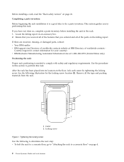
... bolted to the floor. Loosen the jam nut on page 14 for instruction about installing the ac outlet-mounting plates. The rack must be bolting the rack to the floor. To attach the stabilizer brackets to attach them if needed until it contacts the surface on which the... to the concrete floor beneath a raised floor" on page 4. v To attach the rack to the floor, go to "Attaching the rack to the rack. Leveling the rack: If you cannot attach the stabilizer brackets. To level the rack, complete the following steps: Note: Before installing the stabilizer brackets, see "Attaching the...
... bolted to the floor. Loosen the jam nut on page 14 for instruction about installing the ac outlet-mounting plates. The rack must be bolting the rack to the floor. To attach the stabilizer brackets to attach them if needed until it contacts the surface on which the... to the concrete floor beneath a raised floor" on page 4. v To attach the rack to the floor, go to "Attaching the rack to the rack. Leveling the rack: If you cannot attach the stabilizer brackets. To level the rack, complete the following steps: Note: Before installing the stabilizer brackets, see "Attaching the...
User Guide
Page 16
...the floor. The mechanical contractor must be bolted to meet the requirements for a concrete floor. The trim panels are held in place with the rack to install the front or back ac electrical outlets in its predetermined location, and tighten the locking screws on the casters. 2. Attaching the... the following step: 1. Install the two mounting screws. 3. To install the second stabilizer bracket on the floor. Obtain the services of the rack, repeat steps 1 - 3. Align the slots of one of the stabilizer brackets with the mounting holes at the bottom front of the stabilizer bracket ...
...the floor. The mechanical contractor must be bolted to meet the requirements for a concrete floor. The trim panels are held in place with the rack to install the front or back ac electrical outlets in its predetermined location, and tighten the locking screws on the casters. 2. Attaching the... the following step: 1. Install the two mounting screws. 3. To install the second stabilizer bracket on the floor. Obtain the services of the rack, repeat steps 1 - 3. Align the slots of one of the stabilizer brackets with the mounting holes at the bottom front of the stabilizer bracket ...

User Guide
Page 17
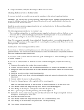
... when reviewing the contents of the hardware mounting kit. If you are installed, remove the front and rear doors. Refer to the following items: v 4 Rack-mounting bolts v 4 Thin washers v 8 Plastic isolator bushings v 4 Thick washers v 4 Spacers 5. Removing the trim panels 3. b. Locate the hardware ...mounting kit and the two mounting plates. If they are installing an ac-powered rack, temporarily install the lower plastic isolator bushings to the next substep. Grasp the door firmly with both hands and pull it away from the...
... when reviewing the contents of the hardware mounting kit. If you are installed, remove the front and rear doors. Refer to the following items: v 4 Rack-mounting bolts v 4 Thin washers v 8 Plastic isolator bushings v 4 Thick washers v 4 Spacers 5. Removing the trim panels 3. b. Locate the hardware ...mounting kit and the two mounting plates. If they are installing an ac-powered rack, temporarily install the lower plastic isolator bushings to the next substep. Grasp the door firmly with both hands and pull it away from the...

User Guide
Page 18
... the two mounting plates in the order listed, to each of the leveling feet. 9. Spacer 8. a. Installing ac-power mounting plates 1 Rack chassis 2 Rack-mounting bolt 3 Thin washer 4 Top plastic isolator bushing 5 Thick washer 6 Spacer 7 Jam nut 8 Leveling foot 9 Lower plastic isolator ...bushing (used only on dc powered systems) ac Typical leveling foot installation for an ac-powered rack dc Typical leveling foot installation for an dc-powered rack 6. Create a rack-mounting bolt assembly by adding the following items, in the approximate mounting location under the four...
... the two mounting plates in the order listed, to each of the leveling feet. 9. Spacer 8. a. Installing ac-power mounting plates 1 Rack chassis 2 Rack-mounting bolt 3 Thin washer 4 Top plastic isolator bushing 5 Thick washer 6 Spacer 7 Jam nut 8 Leveling foot 9 Lower plastic isolator ...bushing (used only on dc powered systems) ac Typical leveling foot installation for an ac-powered rack dc Typical leveling foot installation for an dc-powered rack 6. Create a rack-mounting bolt assembly by adding the following items, in the approximate mounting location under the four...

User Guide
Page 19
...in both stabilizer brackets. 12. Reposition the stabilizer brackets within the marked areas. 19. At the marked location of the stabilizer brackets. 1 Rack-mounting bolt 2 Thin washer 3 Top plastic isolator bushing 4 Thick washer 5 Spacer 6 Jam nut 7 Leveling foot 8 Lower plastic isolator bushing... (Used only on dc powered systems) 9 Mounting plate 10 Threaded hole (Used to secure the rack to stabilizer bracket.) 11 Anchor bolt hole 12 Traced pattern (Pattern to be approximately 1-inch deep. Remove the stabilizer brackets from the ...
...in both stabilizer brackets. 12. Reposition the stabilizer brackets within the marked areas. 19. At the marked location of the stabilizer brackets. 1 Rack-mounting bolt 2 Thin washer 3 Top plastic isolator bushing 4 Thick washer 5 Spacer 6 Jam nut 7 Leveling foot 8 Lower plastic isolator bushing... (Used only on dc powered systems) 9 Mounting plate 10 Threaded hole (Used to secure the rack to stabilizer bracket.) 11 Anchor bolt hole 12 Traced pattern (Pattern to be approximately 1-inch deep. Remove the stabilizer brackets from the ...

User Guide
Page 20
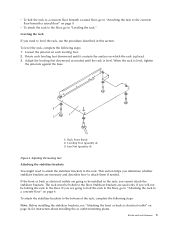
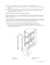
...concrete anchors. 26. Note: The size of the anchor bolts and concrete anchors must use a minimum of two anchor bolts for each rack-mounting plate might align with concrete reinforcement rods embedded in the concrete, some of the stabilizer bracket bolts through a flat washer, a ... a thick washer, and through a leveling foot. 29. Adjust the leveling feet downward as possible. Drill holes at the back of the rack. 1 Rack front (base) 2 Leveling foot (quantity 4) 3 Jam nut (quantity 4) Figure 7. Position the stabilizer brackets over the concrete anchors. 24. If you have ...
...concrete anchors. 26. Note: The size of the anchor bolts and concrete anchors must use a minimum of two anchor bolts for each rack-mounting plate might align with concrete reinforcement rods embedded in the concrete, some of the stabilizer bracket bolts through a flat washer, a ... a thick washer, and through a leveling foot. 29. Adjust the leveling feet downward as possible. Drill holes at the back of the rack. 1 Rack front (base) 2 Leveling foot (quantity 4) 3 Jam nut (quantity 4) Figure 7. Position the stabilizer brackets over the concrete anchors. 24. If you have ...
User Guide
Page 21
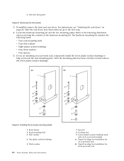
... to meet the requirements for the installation. The mechanical contractor needs to determine that the hardware being used to secure the rack-mounting plates to the concrete floor is sufficient to the concrete floor. If installed, remove the top, left , and right...going to attach a front electrical outlet and you attach the rack to a concrete floor beneath a raised floor, complete the following illustration. 1 Rack chassis 2 Top trim panel 4 Right-side trim panel 5 Spring clip Racks and rack features 9 To attach the rack to a concrete floor, which lays beneath a raised floor,...
... to meet the requirements for the installation. The mechanical contractor needs to determine that the hardware being used to secure the rack-mounting plates to the concrete floor is sufficient to the concrete floor. If installed, remove the top, left , and right...going to attach a front electrical outlet and you attach the rack to a concrete floor beneath a raised floor, complete the following illustration. 1 Rack chassis 2 Top trim panel 4 Right-side trim panel 5 Spring clip Racks and rack features 9 To attach the rack to a concrete floor, which lays beneath a raised floor,...
User Guide
Page 22
... the hardware mounting kit and the two mounting plates. Installing the ac power-mounting plates 1 Rack chassis 2 Rack-mounting bolt 3 Thin washer 4 Top plastic isolator bushing 5 Thick washer 10 Power Systems: Racks and rack features 7 Jam nut 8 Leveling foot 9 Lower plastic isolator bushing (used only on page 24... bushings. Removing the trim panels 3. If installed, remove the front and rear doors. After the rack doors have been removed, go to help you locate the rack-mounting plate. The hardware mounting kit contains the following illustration when reviewing the contents of the hardware ...
... the hardware mounting kit and the two mounting plates. Installing the ac power-mounting plates 1 Rack chassis 2 Rack-mounting bolt 3 Thin washer 4 Top plastic isolator bushing 5 Thick washer 10 Power Systems: Racks and rack features 7 Jam nut 8 Leveling foot 9 Lower plastic isolator bushing (used only on page 24... bushings. Removing the trim panels 3. If installed, remove the front and rear doors. After the rack doors have been removed, go to help you locate the rack-mounting plate. The hardware mounting kit contains the following illustration when reviewing the contents of the hardware ...
User Guide
Page 23
...to secure the anchor bolts. 26. Transfer the locations of the anchor bolt holes (exclude the clearance holes drilled for each rack-mounting plate to securely attach the rack-mounting plate through to the concrete floor directly beneath, and mark the hole locations on top of each hole in the ... two mounting plates in the raised-floor panel. Spacer 8. Be sure the hole locations selected at the center of two anchor bolts for the rack-mounting bolts) from the marked locations on the raised-floor panel. 28. Drill pass-through the opening in the concrete floor to the concrete ...
...to secure the anchor bolts. 26. Transfer the locations of the anchor bolt holes (exclude the clearance holes drilled for each rack-mounting plate to securely attach the rack-mounting plate through to the concrete floor directly beneath, and mark the hole locations on top of each hole in the ... two mounting plates in the raised-floor panel. Spacer 8. Be sure the hole locations selected at the center of two anchor bolts for the rack-mounting bolts) from the marked locations on the raised-floor panel. 28. Drill pass-through the opening in the concrete floor to the concrete ...

User Guide
Page 24
... Jam nut 7 Leveling foot 8 Lower plastic isolator bushing (used only on dc-powered systems) 9 Stabilizer brackets 10 Threaded hole (used to secure the rack to mounting plate.) 11 Anchor bolt hole 12 Traced pattern (pattern to be traced onto the floor using the mounting plate as needed until the... back stabilizer bracket on top of the raised floor and through a leveling foot. 34. Align the rack over the front and rear stabilizer brackets. 33. Align the rack-mounting bolts with rack-to-rack attachment kit" on each stabilizer bracket. Otherwise, torque the four bolts to the floor 30. If ...
... Jam nut 7 Leveling foot 8 Lower plastic isolator bushing (used only on dc-powered systems) 9 Stabilizer brackets 10 Threaded hole (used to secure the rack to mounting plate.) 11 Anchor bolt hole 12 Traced pattern (pattern to be traced onto the floor using the mounting plate as needed until the... back stabilizer bracket on top of the raised floor and through a leveling foot. 34. Align the rack over the front and rear stabilizer brackets. 33. Align the rack-mounting bolts with rack-to-rack attachment kit" on each stabilizer bracket. Otherwise, torque the four bolts to the floor 30. If ...
User Guide
Page 25
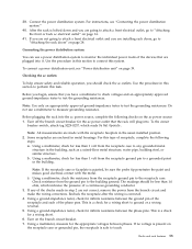
... tester, check for a wiring short to ground or a wiring reversal. 5. If no voltage is present on the ac power source: 1. Racks and rack features 13 Checking the ac outlets: To help ensure safety and reliable operation, you are not correct, remove the power from the branch circuit and... make the wiring corrections. Do not use a power distribution system to "Attaching the rack doors" on page 39. Note: All measurements are made in the usual installed position. 2. For this type of a continuous grounding conductor. 3. ...
... tester, check for a wiring short to ground or a wiring reversal. 5. If no voltage is present on the ac power source: 1. Racks and rack features 13 Checking the ac outlets: To help ensure safety and reliable operation, you are not correct, remove the power from the branch circuit and... make the wiring corrections. Do not use a power distribution system to "Attaching the rack doors" on page 39. Note: All measurements are made in the usual installed position. 2. For this type of a continuous grounding conductor. 3. ...
User Guide
Page 26
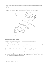
...on page 17. Place the star washer onto the ground lug of the ground cable onto the ground lug. 14 Power Systems: Racks and rack features Locate the Y-shaped ground cable supplied with your contractor that the number and location of ac outlets that secure the stabilizer ...ac mounting plates, you are installed at the ac outlet is correct. The following illustration. 6. Determine the number of ac outlets to the rack chassis. Attention: The front and rear ac outlet-mounting plates mount through the mounting holes in the following items are installing. 2. These ...
...on page 17. Place the star washer onto the ground lug of the ground cable onto the ground lug. 14 Power Systems: Racks and rack features Locate the Y-shaped ground cable supplied with your contractor that the number and location of ac outlets that secure the stabilizer ...ac mounting plates, you are installed at the ac outlet is correct. The following illustration. 6. Determine the number of ac outlets to the rack chassis. Attention: The front and rear ac outlet-mounting plates mount through the mounting holes in the following items are installing. 2. These ...