
User Guide
Page 13
...significantly changed information in Common procedures for both PDU and PDU+ models. What's new in Enclosures and expansion units. - Installing the 7014-T00 and 7014-T42 racks Use this service. v Topic collections that included installation information ...racks and rack features. October 2012 Content updates include the following : v Miscellaneous changes were made to install the related components of this rack, see model-specific installation topics in Racks and rack features Read about planning and installing the IBM PureFlex™ System 42U Rack (7953-94X) and the IBM 42U Slim Rack...
...significantly changed information in Common procedures for both PDU and PDU+ models. What's new in Enclosures and expansion units. - Installing the 7014-T00 and 7014-T42 racks Use this service. v Topic collections that included installation information ...racks and rack features. October 2012 Content updates include the following : v Miscellaneous changes were made to install the related components of this rack, see model-specific installation topics in Racks and rack features Read about planning and installing the IBM PureFlex™ System 42U Rack (7953-94X) and the IBM 42U Slim Rack...
User Guide
Page 34
... 30. Replacing the side panel 3. For racks that use trim panels instead of doors, a reduced-interference panel type must be installed when certain expansion unit models are present. Removing the 7014-T00 or 7014-T42 trim panels: For racks that use trim panels, a reduced-interference ...panel type must install a securing screw into place and close the locking latches. Removing and replacing 7014-T00 or 7014-T42 trim panels Racks that was installed...
... 30. Replacing the side panel 3. For racks that use trim panels instead of doors, a reduced-interference panel type must be installed when certain expansion unit models are present. Removing the 7014-T00 or 7014-T42 trim panels: For racks that use trim panels, a reduced-interference ...panel type must install a securing screw into place and close the locking latches. Removing and replacing 7014-T00 or 7014-T42 trim panels Racks that was installed...

User Guide
Page 35
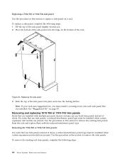
Replacing the 7014-T00 or 7014-T42 trim panels: For racks that hold the panel in place. 3. Removing the rack trim panel 2. Squeeze inward firmly with your hands in this procedure to replace the trim panels. Figure 21. Rotate your fingertips to release the spring ... rack features 23 Repeat this section to remove the left side trim panel. Lift the panel out and set it aside. 5. 1. Place both hands on the center of doors, a reduced-interference panel type must be installed when certain expansion unit models are present. Use the procedure in slightly until the panel is...
Replacing the 7014-T00 or 7014-T42 trim panels: For racks that hold the panel in place. 3. Removing the rack trim panel 2. Squeeze inward firmly with your hands in this procedure to replace the trim panels. Figure 21. Rotate your fingertips to release the spring ... rack features 23 Repeat this section to remove the left side trim panel. Lift the panel out and set it aside. 5. 1. Place both hands on the center of doors, a reduced-interference panel type must be installed when certain expansion unit models are present. Use the procedure in slightly until the panel is...

User Guide
Page 46
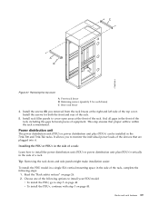
... first two standoffs in the upper-left and lower-right corners of the first rack as shown in Figure 32. Position the racks together. 8. You might need to adjust the leveling feet to connect multiple racks 5. Install the second two standoffs in the upper-left and lower-right corners of...foam as shown in Figure 32. 6. Align the standoff holes. Location of the rack. Removing the side panels, Z and J brackets, and installing standoffs and long foam to do this. 34 Power Systems: Racks and rack features 4. For a model T42 rack, join the short foam to the end of the long foam, and adhere ...
... first two standoffs in the upper-left and lower-right corners of the first rack as shown in Figure 32. Position the racks together. 8. You might need to adjust the leveling feet to connect multiple racks 5. Install the second two standoffs in the upper-left and lower-right corners of...foam as shown in Figure 32. 6. Align the standoff holes. Location of the rack. Removing the side panels, Z and J brackets, and installing standoffs and long foam to do this. 34 Power Systems: Racks and rack features 4. For a model T42 rack, join the short foam to the end of the long foam, and adhere ...
User Guide
Page 51
... 26. 2. Read the "Rack safety notices" on page 40. Racks and rack features 39 Install the screws (B) you to cover open areas at the right and left side of the rack. To install the PDU model in a single EIA vertical mounting space in the 7014-T00 and 7014-T42 racks. Figure 37. Installing the... PDU or PDU+ in the side of the rack. 5. Removing the top cover A Front rack brace B Retaining screws (quantity 2 for ...
... 26. 2. Read the "Rack safety notices" on page 40. Racks and rack features 39 Install the screws (B) you to cover open areas at the right and left side of the rack. To install the PDU model in a single EIA vertical mounting space in the 7014-T00 and 7014-T42 racks. Figure 37. Installing the... PDU or PDU+ in the side of the rack. 5. Removing the top cover A Front rack brace B Retaining screws (quantity 2 for ...