

Owners Manual
Page 6
... are working properly (See the Operation and Maintenance sections in this manual. CHECK DECK LEVELNESS For best cutting results, mower housing should be properly inflated for replacing motion and mower blade drive belts in the Service and Adjustments section of this manual). ✓ It is filled...tire pressure to PSI shown on your tractor, check to operate your tractor were overinflated at the factory). ✓ Be sure mower deck is in "transmission engaged" position (see that all connections are still secure and wires are routed properly around pulleys and inside all ...
... are working properly (See the Operation and Maintenance sections in this manual. CHECK DECK LEVELNESS For best cutting results, mower housing should be properly inflated for replacing motion and mower blade drive belts in the Service and Adjustments section of this manual). ✓ It is filled...tire pressure to PSI shown on your tractor, check to operate your tractor were overinflated at the factory). ✓ Be sure mower deck is in "transmission engaged" position (see that all connections are still secure and wires are routed properly around pulleys and inside all ...

Owners Manual
Page 17
...Fig. 17 CLEANING • Clean engine, battery, seat, finish, etc. Debris can restrict clutch/brake pedal shaft movement, causing belt slip and loss of the mower deck. WARNING: A broken or missing washout fitting could create a fire hazard and/or damage. Water in engine or immediately, prior to... (See Fig. 17) The fuel filter should be replaced once each use. 1. Thread the nozzle adapter (packaged with the cutting deck engaged until the deck is required. • With engine cool, remove filter and plug fuel line sections. • Place new fuel filter in position in...
...Fig. 17 CLEANING • Clean engine, battery, seat, finish, etc. Debris can restrict clutch/brake pedal shaft movement, causing belt slip and loss of the mower deck. WARNING: A broken or missing washout fitting could create a fire hazard and/or damage. Water in engine or immediately, prior to... (See Fig. 17) The fuel filter should be replaced once each use. 1. Thread the nozzle adapter (packaged with the cutting deck engaged until the deck is required. • With engine cool, remove filter and plug fuel line sections. • Place new fuel filter in position in...

Owners Manual
Page 19
...LOCATION TRANSAXLE BRACKET (T) LOCATED BETWEEN REAR TIRES TRANSAXLE 02965 BACK Q. SLIDE MOWER UNDER TRACTOR (See Fig. 25) • Bring belt forward and check belt for anti-sway bar will go and position mower on right side of bar into hole in rear mower bracket (D). Insert integrated washer...shown but hole for proper routing in same position/location. • Pivot the integrated washer end of anti-sway bar (S) towards mower deck bracket on right side of tractor with small washer and small retainer spring as needed to the right. FRONT MOWER BRACKET W. A A. ...
...LOCATION TRANSAXLE BRACKET (T) LOCATED BETWEEN REAR TIRES TRANSAXLE 02965 BACK Q. SLIDE MOWER UNDER TRACTOR (See Fig. 25) • Bring belt forward and check belt for anti-sway bar will go and position mower on right side of bar into hole in rear mower bracket (D). Insert integrated washer...shown but hole for proper routing in same position/location. • Pivot the integrated washer end of anti-sway bar (S) towards mower deck bracket on right side of tractor with small washer and small retainer spring as needed to the right. FRONT MOWER BRACKET W. A A. ...

Owners Manual
Page 20
NOTE: Requires deck lifting. FRONT LIFT LINK ASSEMBLY F. ENGINE CLUTCH PULLEY Fig. 31 9 INSTALL BELT ON ENGINE CLUTCH PULLEY (M) (See Fig. 31 & 32) • Disengage belt tension rod (K) from locking bracket (L). • Install belt onto engine clutch pulley (M). MOWER SIDE SUSPENSION ARMS ... RIGHT SIDE REAR MOWER BRACKET Fig. 29 7. sembly over pin on outside of tractor. U C M F G E H J E. CAUTION: Belt tension rod is spring loaded. SERVICE AND ADJUSTMENTS 6. FRONT MOWER BRACKET J. RIGHT SIDE REAR MOWER BRACKET U. SMALL RETAINER SPRING M. M. FRONT LINK ...
NOTE: Requires deck lifting. FRONT LIFT LINK ASSEMBLY F. ENGINE CLUTCH PULLEY Fig. 31 9 INSTALL BELT ON ENGINE CLUTCH PULLEY (M) (See Fig. 31 & 32) • Disengage belt tension rod (K) from locking bracket (L). • Install belt onto engine clutch pulley (M). MOWER SIDE SUSPENSION ARMS ... RIGHT SIDE REAR MOWER BRACKET Fig. 29 7. sembly over pin on outside of tractor. U C M F G E H J E. CAUTION: Belt tension rod is spring loaded. SERVICE AND ADJUSTMENTS 6. FRONT MOWER BRACKET J. RIGHT SIDE REAR MOWER BRACKET U. SMALL RETAINER SPRING M. M. FRONT LINK ...

Owners Manual
Page 21
...hands with gloves and/or wrap blade with the results. CAUTION: Belt tension rod is spring loaded. Securely tighten all mandrel pulleys (R) and around mandrels and entire upper deck surface. • Remove belt from mandrel covers (Q) and remove covers. • Remove any ...dirt or grass clippings which side of mower you wish to adjust. • With a 3/4" or adjustable wrench, turn of blade to the ground. CAUTION: Belt tension rod is spring loaded. P...
...hands with gloves and/or wrap blade with the results. CAUTION: Belt tension rod is spring loaded. Securely tighten all mandrel pulleys (R) and around mandrels and entire upper deck surface. • Remove belt from mandrel covers (Q) and remove covers. • Remove any ...dirt or grass clippings which side of mower you wish to adjust. • With a 3/4" or adjustable wrench, turn of blade to the ground. CAUTION: Belt tension rod is spring loaded. P...

Owners Manual
Page 22
...-rotation link (B) on bottom side of the blade. BELT INSTALLATION - 1. TIGHTEN ADJUST NUT B TO RAISE MOWER 02950 LOOSEN JAM NUT A FIRST LOOSEN ADJUST NUT B TO LOWER MOWER Fig. 37 22 FRONT-TO-BACK ADJUSTMENT (See Figs. 36 & 37) IMPORTANT: Deck must be adjusted so the front tip is 1/8" to... 1/2" lower than the rear tip when the mower is in this manual). Pull belt toward rear of tractor and roll belt around transmission cooling fan and onto the input pulley (F). ...
...-rotation link (B) on bottom side of the blade. BELT INSTALLATION - 1. TIGHTEN ADJUST NUT B TO RAISE MOWER 02950 LOOSEN JAM NUT A FIRST LOOSEN ADJUST NUT B TO LOWER MOWER Fig. 37 22 FRONT-TO-BACK ADJUSTMENT (See Figs. 36 & 37) IMPORTANT: Deck must be adjusted so the front tip is 1/8" to... 1/2" lower than the rear tip when the mower is in this manual). Pull belt toward rear of tractor and roll belt around transmission cooling fan and onto the input pulley (F). ...

Owners Manual
Page 27
...not corrected, contact an authorized service center/ department. Worn/damaged mower drive belt. 3. Replace blade mandrel. 5. Remove obstruction. 2. Tighten blade bolt. 7. Blades improperly installed. 9. Clogged mower deck vent holes from buildup of grass, leaves, trash under mower. 4. Bulb...mandrel. 5. Obstruction in transmission during shipment or servicing. 5. Replace mower drive belt. 3. Place throttle control in "engaged" position. 2. Allow grass to open vent holes. 1. Level mower deck. 5. Reinstall blades sharp edge down. 10. Check/replace light switch. 4. ...
...not corrected, contact an authorized service center/ department. Worn/damaged mower drive belt. 3. Replace blade mandrel. 5. Remove obstruction. 2. Tighten blade bolt. 7. Blades improperly installed. 9. Clogged mower deck vent holes from buildup of grass, leaves, trash under mower. 4. Bulb...mandrel. 5. Obstruction in transmission during shipment or servicing. 5. Replace mower drive belt. 3. Place throttle control in "engaged" position. 2. Allow grass to open vent holes. 1. Level mower deck. 5. Reinstall blades sharp edge down. 10. Check/replace light switch. 4. ...
Owners Manual
Page 41
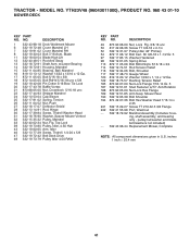
YTH23V48 (96043011000), PRODUCT NO. 960 43 01-10 MOWER DECK KEY PART NO. DESCRIPTION 1 532 43 98-18 Deck Weldment Mower 6 532 19 72-48 Cover Mandrel LH 7 532 19 91-02 Cover Mandrel RH 8 532 19 30-03 Bolt 7/16 Asm. Blade 11 ...-80 Pulley, Idler, 4.50 Hub 43 532 19 60-65 Arm, Idler 46 532 13 77-29 Screw, Thdroll. 1/4-20 x 5/8 47 532 19 72-42 Belt Deck Drive 48 532 19 73-79 Pulley Idler 4.50 RAW KEY PART NO. ing, shaft assembly, and bearing only - inches 1 inch = 25.4 mm 41 DESCRIPTION...
YTH23V48 (96043011000), PRODUCT NO. 960 43 01-10 MOWER DECK KEY PART NO. DESCRIPTION 1 532 43 98-18 Deck Weldment Mower 6 532 19 72-48 Cover Mandrel LH 7 532 19 91-02 Cover Mandrel RH 8 532 19 30-03 Bolt 7/16 Asm. Blade 11 ...-80 Pulley, Idler, 4.50 Hub 43 532 19 60-65 Arm, Idler 46 532 13 77-29 Screw, Thdroll. 1/4-20 x 5/8 47 532 19 72-42 Belt Deck Drive 48 532 19 73-79 Pulley Idler 4.50 RAW KEY PART NO. ing, shaft assembly, and bearing only - inches 1 inch = 25.4 mm 41 DESCRIPTION...

Owners Manual
Page 48
... to left Rental *** "Limited Lifetime Warranty" on specific Snow Throwers & Tillers, warranty through Husqvarna. ** See reference 1 (b) of the warranty statement. EZ - Two (2) Year Consumer warranty...arigculutral, or income producing Product/Component use, other than Rental Use) Front Mounted Deck Riders Engine* * * Transmission 2 Years NO WARRANTY Battery 1 Year Pro-...if purchased) Accessories (e.g., grass catcher, bumper guard accessories, etc. 1 Year NO WARRANTY Parts (e.g., belts, blades, etc.) 30 days NO WARRANTY Parts & Accessories (if replaced in the U.S.A. Two ...
... to left Rental *** "Limited Lifetime Warranty" on specific Snow Throwers & Tillers, warranty through Husqvarna. ** See reference 1 (b) of the warranty statement. EZ - Two (2) Year Consumer warranty...arigculutral, or income producing Product/Component use, other than Rental Use) Front Mounted Deck Riders Engine* * * Transmission 2 Years NO WARRANTY Battery 1 Year Pro-...if purchased) Accessories (e.g., grass catcher, bumper guard accessories, etc. 1 Year NO WARRANTY Parts (e.g., belts, blades, etc.) 30 days NO WARRANTY Parts & Accessories (if replaced in the U.S.A. Two ...

Parts Manual
Page 15
...43 532 19 60-65 Arm, Idler 46 532 13 77-29 Screw, Thdroll. 1/4-20 x 5/8 47 532 19 72-42 Belt Deck Drive 48 532 19 73-79 Pulley Idler 4.50 RAW KEY PART NO. Sh 3/8-16 x 1-1/2 Gr. 5 97 532 17... - - 532 43 96-44 Replacement Mower, Complete NOTE: All component dimensions given in U.S. DESCRIPTION 1 532 44 00-48 Deck Weldment Mower 6 532 19 72-48 Cover Mandrel LH 7 532 19 91-02 Cover Mandrel RH 8 532 19 30-03 Bolt... 12 532 40 48-51 Rod Anti-Sway 13 532 18 72-91 Shaft Asm. YTH23V48 (96043012500), PRODUCT NO. 960 43 01-25 MOWER DECK KEY PART NO. DESCRIPTION 49 873 90 06-00 Nut, Lock Flg. 3/8-16 unc...
...43 532 19 60-65 Arm, Idler 46 532 13 77-29 Screw, Thdroll. 1/4-20 x 5/8 47 532 19 72-42 Belt Deck Drive 48 532 19 73-79 Pulley Idler 4.50 RAW KEY PART NO. Sh 3/8-16 x 1-1/2 Gr. 5 97 532 17... - - 532 43 96-44 Replacement Mower, Complete NOTE: All component dimensions given in U.S. DESCRIPTION 1 532 44 00-48 Deck Weldment Mower 6 532 19 72-48 Cover Mandrel LH 7 532 19 91-02 Cover Mandrel RH 8 532 19 30-03 Bolt... 12 532 40 48-51 Rod Anti-Sway 13 532 18 72-91 Shaft Asm. YTH23V48 (96043012500), PRODUCT NO. 960 43 01-25 MOWER DECK KEY PART NO. DESCRIPTION 49 873 90 06-00 Nut, Lock Flg. 3/8-16 unc...

Parts Manual
Page 20
...or including any of the following are NOT considered defects in your Husqvarna unit to an authorized Husqvarna Servicing Dealer/Center and arrange for the deck shell only mechanical components/parts such as belts, pulleys, spindle housings, bearings, blades, rods, height adjusters, caster...Armor Protected) 10 Year Limited & Fabricated Limited Lifetime, Deck Warranties. You must maintain and present Proof of purchase (including date, product model and, if applicable, engine serial number) to an authorized Husqvarna Servicing Dealer for warranty service under this Limited Warranty, you...
...or including any of the following are NOT considered defects in your Husqvarna unit to an authorized Husqvarna Servicing Dealer/Center and arrange for the deck shell only mechanical components/parts such as belts, pulleys, spindle housings, bearings, blades, rods, height adjusters, caster...Armor Protected) 10 Year Limited & Fabricated Limited Lifetime, Deck Warranties. You must maintain and present Proof of purchase (including date, product model and, if applicable, engine serial number) to an authorized Husqvarna Servicing Dealer for warranty service under this Limited Warranty, you...

Parts Manual
Page 22
...accessory that was replaced. Armor Protected Stamped Deck Shell Example Below Fabricated Deck Shell Example Below Armor Protected Stamped Deck Shell Reinforced area Stamped Deck Shell below, NOT reinforced No reinforced area... date of the warranty statement. Two (2) Year Consumer warranty, parts & labor, with Husqvarna. Two (2) Year Consumer warranty, parts & labor, with Hydro-Gear Distributor network. *** "Limited Lifetime Warranty..., etc. 1 Year No Warranty No Warranty Parts (e.g., belts, blades, etc.) 30 days No Warranty No Warranty Parts & Accessories (if replaced in the U.S.A.
...accessory that was replaced. Armor Protected Stamped Deck Shell Example Below Fabricated Deck Shell Example Below Armor Protected Stamped Deck Shell Reinforced area Stamped Deck Shell below, NOT reinforced No reinforced area... date of the warranty statement. Two (2) Year Consumer warranty, parts & labor, with Husqvarna. Two (2) Year Consumer warranty, parts & labor, with Hydro-Gear Distributor network. *** "Limited Lifetime Warranty..., etc. 1 Year No Warranty No Warranty Parts (e.g., belts, blades, etc.) 30 days No Warranty No Warranty Parts & Accessories (if replaced in the U.S.A.


