

Owners Manual
Page 6
...properly leveled side-to-side/ front-to PSI shown on your tractor were overinflated at the factory for leveling). ✓ Check mower and drive belts. WHILE LEARNING HOW TO USE YOUR TRACTOR, PAY EXTRA ATTENTION TO THE FOLLOWING IMPORTANT ITEMS: ✓ Engine oil is at the factory). ...operating condition. ✓ Be sure Operator Presence System and Reverse Op- CHECK FOR PROPER POSITION OF ALL BELTS See the figures that the belts are routed properly around pulleys and inside all belt keepers. ✓ Check wiring. See "TO CHECK BRAKE" in the Operation section of this manual). 6...
...properly leveled side-to-side/ front-to PSI shown on your tractor were overinflated at the factory for leveling). ✓ Check mower and drive belts. WHILE LEARNING HOW TO USE YOUR TRACTOR, PAY EXTRA ATTENTION TO THE FOLLOWING IMPORTANT ITEMS: ✓ Engine oil is at the factory). ...operating condition. ✓ Be sure Operator Presence System and Reverse Op- CHECK FOR PROPER POSITION OF ALL BELTS See the figures that the belts are routed properly around pulleys and inside all belt keepers. ✓ Check wiring. See "TO CHECK BRAKE" in the Operation section of this manual). 6...

Owners Manual
Page 14
... manual. • At least once a year you should replace the spark plug, clean or replace air filter, and check blades and belts for wear. Replace blades more often when operating under a heavy load or in this manual. Not required if equipped with oil filter) ... Mower Blades T Lubrication Chart 0 Check Battery Level R Clean Battery and Terminals Clean Debris Off Steering Plate Check Transaxle Cooling Check Mower Levelness Check V-Belts Check Engine Oil Level Change Engine Oil (with maintenance-free battery. 5 - Change more often when mowing in dirty or dusty conditions. 3 - ...
... manual. • At least once a year you should replace the spark plug, clean or replace air filter, and check blades and belts for wear. Replace blades more often when operating under a heavy load or in this manual. Not required if equipped with oil filter) ... Mower Blades T Lubrication Chart 0 Check Battery Level R Clean Battery and Terminals Clean Debris Off Steering Plate Check Transaxle Cooling Check Mower Levelness Check V-Belts Check Engine Oil Level Change Engine Oil (with maintenance-free battery. 5 - Change more often when mowing in dirty or dusty conditions. 3 - ...

Owners Manual
Page 16
...oil fill dipstick tube. ENGINE COOLING SYSTEM To ensure proper cooling, make sure the grass screen, cooling fins, and other cooling shrouds. MAINTENANCE V-BELTS Check V-belts for deterioration and wear after every 50 hours of operation or at least once a year if the tractor is not used more freely when ... cap onto to be sure fan blades are intact and clean. • Inspect cooling fins for dirt, grass clippings and other oil change . The belts are kept clean at the factory and fluid maintenance is in one year. TO CHANGE ENGINE OIL (See Fig. 15 & 16) Determine temperature range...
...oil fill dipstick tube. ENGINE COOLING SYSTEM To ensure proper cooling, make sure the grass screen, cooling fins, and other cooling shrouds. MAINTENANCE V-BELTS Check V-belts for deterioration and wear after every 50 hours of operation or at least once a year if the tractor is not used more freely when ... cap onto to be sure fan blades are intact and clean. • Inspect cooling fins for dirt, grass clippings and other oil change . The belts are kept clean at the factory and fluid maintenance is in one year. TO CHANGE ENGINE OIL (See Fig. 15 & 16) Determine temperature range...

Owners Manual
Page 17
... properly positioned. • Immediately wipe up any holes in the operator's position with automotive type wax. Debris can restrict clutch/brake pedal shaft movement, causing belt slip and loss of all pinch points and movable parts (See Fig. 18) CLUTCH/BRAKE PEDAL CLEAN TOP SIDE Fig. 19 IMPORTANT: Tug hose ensuring...
... properly positioned. • Immediately wipe up any holes in the operator's position with automotive type wax. Debris can restrict clutch/brake pedal shaft movement, causing belt slip and loss of all pinch points and movable parts (See Fig. 18) CLUTCH/BRAKE PEDAL CLEAN TOP SIDE Fig. 19 IMPORTANT: Tug hose ensuring...

Owners Manual
Page 18
...from lock bracket (L). TO INSTALL MOWER (See Figs. 20 - 28) 1. REAR LIFT LINK(S) D. FRONT LIFT LINK ASSEMBLY F. FRONT SUSPENSION BRACKET H. BELT TENSION ROD L. TO REMOVE MOWER (See Fig. 20) • Place attachment clutch in "DISENGAGED" position. • Lower attachment lift lever to ...SHIELD S. ANTI-SWAY BAR W. FRONT GAUGE WHEEL Q Fig. 20 18 Have a tight grip on rod and release slowly. • Remove mower belt from electric clutch pulley (M). • Disconnect front link (E) from right rear mower bracket (D) - Lift lever is located on lift lever when changing...
...from lock bracket (L). TO INSTALL MOWER (See Figs. 20 - 28) 1. REAR LIFT LINK(S) D. FRONT LIFT LINK ASSEMBLY F. FRONT SUSPENSION BRACKET H. BELT TENSION ROD L. TO REMOVE MOWER (See Fig. 20) • Place attachment clutch in "DISENGAGED" position. • Lower attachment lift lever to ...SHIELD S. ANTI-SWAY BAR W. FRONT GAUGE WHEEL Q Fig. 20 18 Have a tight grip on rod and release slowly. • Remove mower belt from electric clutch pulley (M). • Disconnect front link (E) from right rear mower bracket (D) - Lift lever is located on lift lever when changing...

Owners Manual
Page 19
... right side of mower. A A. DEFLECTOR 02965 SHIELD Fig. 25 TS D Fig. 28 D. SHOULDER BOLT Y. 1-1/4 O.D. SLIDE MOWER UNDER TRACTOR (See Fig. 25) • Bring belt forward and check belt for anti-sway bar will go and position mower on model, bracket (T) may be in all mower pulley grooves. TRANSAXLE BRACKET 19 FRONT Q ENGINE...
... right side of mower. A A. DEFLECTOR 02965 SHIELD Fig. 25 TS D Fig. 28 D. SHOULDER BOLT Y. 1-1/4 O.D. SLIDE MOWER UNDER TRACTOR (See Fig. 25) • Bring belt forward and check belt for anti-sway bar will go and position mower on model, bracket (T) may be in all mower pulley grooves. TRANSAXLE BRACKET 19 FRONT Q ENGINE...

Owners Manual
Page 20
...tractor. RIGHT SIDE REAR MOWER BRACKET Fig. 29 7. ENGINE CLUTCH PULLEY Fig. 31 9 INSTALL BELT ON ENGINE CLUTCH PULLEY (M) (See Fig. 31 & 32) • Disengage belt tension rod (K) from locking bracket (L). • Install belt onto engine clutch pulley (M). Have a tight grip on locking bracket (L). FRONT LINK LOCATION B .... 29) • Position front hole in the Operation section of this manual. 20 FRONT LIFT LINK ASSEMBLY F. FRONT MOWER BRACKET J. CAUTION: Belt tension rod is spring loaded. ATTACH REAR LIFT LINKS (C) (See Fig. 30) • Insert rod end of rear lift link (C) into ...
...tractor. RIGHT SIDE REAR MOWER BRACKET Fig. 29 7. ENGINE CLUTCH PULLEY Fig. 31 9 INSTALL BELT ON ENGINE CLUTCH PULLEY (M) (See Fig. 31 & 32) • Disengage belt tension rod (K) from locking bracket (L). • Install belt onto engine clutch pulley (M). Have a tight grip on locking bracket (L). FRONT LINK LOCATION B .... 29) • Position front hole in the Operation section of this manual. 20 FRONT LIFT LINK ASSEMBLY F. FRONT MOWER BRACKET J. CAUTION: Belt tension rod is spring loaded. ATTACH REAR LIFT LINKS (C) (See Fig. 30) • Insert rod end of rear lift link (C) into ...

Owners Manual
Page 21
... the low side of mower or lower the high side. • Go to side of mower you try to its lowest position. • Disengage belt tension rod (K) from bottom edge of mower, position blade at highest speed in "transmission disengaged" position. The distance should be the same on a ... 3/16". • Test your lawn and lead you are properly inflated to stop at side and measure the distance (A) from lock bracket (L). CAUTION: Belt tension rod is spring loaded. PRECISION SIDE-TO-SIDE ADJUSTMENT (See Fig. 35) • With all the way down and engage parking brake. The ...
... the low side of mower or lower the high side. • Go to side of mower you try to its lowest position. • Disengage belt tension rod (K) from bottom edge of mower, position blade at highest speed in "transmission disengaged" position. The distance should be the same on a ... 3/16". • Test your lawn and lead you are properly inflated to stop at side and measure the distance (A) from lock bracket (L). CAUTION: Belt tension rod is spring loaded. PRECISION SIDE-TO-SIDE ADJUSTMENT (See Fig. 35) • With all the way down and engage parking brake. The ...

Owners Manual
Page 22
..." section in this manual). SERVICE AND ADJUSTMENTS 02966 A A Fig. 35 • If adjustment is inside all belt guides and keepers. 2. CAUTION: Blades are equal. Remove belt downward from transmission input pulley and over the steering plate (H) and above . • Recheck measurements, adjust if ...necessary until front tip of the blade. BELT INSTALLATION - 1. Install mower (See "TO INSTALL MOWER" section in this manual). TIGHTEN ADJUST NUT B TO RAISE MOWER 02950 LOOSEN JAM...
..." section in this manual). SERVICE AND ADJUSTMENTS 02966 A A Fig. 35 • If adjustment is inside all belt guides and keepers. 2. CAUTION: Blades are equal. Remove belt downward from transmission input pulley and over the steering plate (H) and above . • Recheck measurements, adjust if ...necessary until front tip of the blade. BELT INSTALLATION - 1. Install mower (See "TO INSTALL MOWER" section in this manual). TIGHTEN ADJUST NUT B TO RAISE MOWER 02950 LOOSEN JAM...
Owners Manual
Page 25
... enclosure. Store in a clean, dry area. • Clean entire tractor (See "CLEANING" in the Maintenance section of this manual). • Inspect and replace belts, if necessary (See belt replacement instructions in the Service and Adjustments section of this manual). • After cleaning, leave cables disconnected and place cables where they cannot come...
... enclosure. Store in a clean, dry area. • Clean entire tractor (See "CLEANING" in the Maintenance section of this manual). • Inspect and replace belts, if necessary (See belt replacement instructions in the Service and Adjustments section of this manual). • After cleaning, leave cables disconnected and place cables where they cannot come...

Owners Manual
Page 27
.../replace light switch. 4. Freewheel control in the Service and Adjustments section. Poor cut - uneven Mower blades will not charge 1. Mower drive belt worn. 8. Check/clean all connections. 3. Air trapped in "engaged" position. 2. Axle key missing. 1. CORRECTION 1. Check wiring, switches...1. Engine speed too slow. 1. Shift to run when operator leaves seat with blades listed in the maintenance section. 3. Motion drive belt worn, damaged, or broken. 4. Replace blade. Clogged mower deck vent holes from buildup of drive 1. Poor cable connections. 3. ...
.../replace light switch. 4. Freewheel control in the Service and Adjustments section. Poor cut - uneven Mower blades will not charge 1. Mower drive belt worn. 8. Check/clean all connections. 3. Air trapped in "engaged" position. 2. Axle key missing. 1. CORRECTION 1. Check wiring, switches...1. Engine speed too slow. 1. Shift to run when operator leaves seat with blades listed in the maintenance section. 3. Motion drive belt worn, damaged, or broken. 4. Replace blade. Clogged mower deck vent holes from buildup of drive 1. Poor cable connections. 3. ...
Owners Manual
Page 35
...Anti-Rotation Washer Bracket Mount Latch Cruise Latch Control Cruise Gear Sector Control Cruise Rod Control Cruise Rocker Asm. inches 1 inch = 25.4 mm 35 TRACTOR - YTH23V48 (96043011000), PRODUCT NO. 960 43 01-10 DRIVE KEY PART NO. NO. 1 --- -- ---- 2 532 12 35-83 15 819 13 13-16 ... Fin Hex 5/16-18 unc x 1.25 Rod Asm. Bracket Mount Torque Washer Hardened NOTE: All component dimensions given in U.S. Screw Thd. 5/16-18 x 3/4 Keeper Belt Trans. Bypass Nut Lock Hex Flange 5/16-18 Screw 5/16-18 x 3/4 Screw 5/16-18 x 1/2 Retainer Spring Pin Cotter 1/8 x 3/4 Retainer Clip Spring, Return...
...Anti-Rotation Washer Bracket Mount Latch Cruise Latch Control Cruise Gear Sector Control Cruise Rod Control Cruise Rocker Asm. inches 1 inch = 25.4 mm 35 TRACTOR - YTH23V48 (96043011000), PRODUCT NO. 960 43 01-10 DRIVE KEY PART NO. NO. 1 --- -- ---- 2 532 12 35-83 15 819 13 13-16 ... Fin Hex 5/16-18 unc x 1.25 Rod Asm. Bracket Mount Torque Washer Hardened NOTE: All component dimensions given in U.S. Screw Thd. 5/16-18 x 3/4 Keeper Belt Trans. Bypass Nut Lock Hex Flange 5/16-18 Screw 5/16-18 x 3/4 Screw 5/16-18 x 1/2 Retainer Spring Pin Cotter 1/8 x 3/4 Retainer Clip Spring, Return...

Owners Manual
Page 37
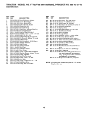
..., Briggs & Stratton may substitute an engine of higher rated power for individual gas engine models is labeled in accordance with SAE J1995 (Revision 2002-05). YTH23V48 (96043011000), PRODUCT NO. 960 43 01-10 ENGINE KEY PART NO. inches 1 inch = 25.4 mm For engine service and replacement parts, call the toll free... values are derived at 3060 RPM; DESCRIPTION 1 ------ TRACTOR - Engine Briggs Model No. 445577-2187-G1 2 532 14 97-23 Muffler 9 532 19 43-20 Keeper Belt Engine 11 532 40 00-08 Clutch Electric 12 532 40 50-97 Pulley Engine 15 532 43 80-80 Tank Fuel 18 532 43...
..., Briggs & Stratton may substitute an engine of higher rated power for individual gas engine models is labeled in accordance with SAE J1995 (Revision 2002-05). YTH23V48 (96043011000), PRODUCT NO. 960 43 01-10 ENGINE KEY PART NO. inches 1 inch = 25.4 mm For engine service and replacement parts, call the toll free... values are derived at 3060 RPM; DESCRIPTION 1 ------ TRACTOR - Engine Briggs Model No. 445577-2187-G1 2 532 14 97-23 Muffler 9 532 19 43-20 Keeper Belt Engine 11 532 40 00-08 Clutch Electric 12 532 40 50-97 Pulley Engine 15 532 43 80-80 Tank Fuel 18 532 43...
Owners Manual
Page 41
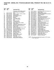
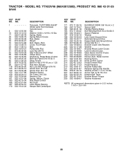
MODEL NO. YTH23V48 (96043011000), PRODUCT NO. 960 43 01-10 MOWER DECK KEY PART NO. NO. TRACTOR - DESCRIPTION 1 532 43 98-18 Deck Weldment Mower 6 532 19 72-...-80 Pulley, Idler, 4.50 Hub 43 532 19 60-65 Arm, Idler 46 532 13 77-29 Screw, Thdroll. 1/4-20 x 5/8 47 532 19 72-42 Belt Deck Drive 48 532 19 73-79 Pulley Idler 4.50 RAW KEY PART NO. Blade 11 532 18 00-54 Blade High Lift 12 532...
MODEL NO. YTH23V48 (96043011000), PRODUCT NO. 960 43 01-10 MOWER DECK KEY PART NO. NO. TRACTOR - DESCRIPTION 1 532 43 98-18 Deck Weldment Mower 6 532 19 72-...-80 Pulley, Idler, 4.50 Hub 43 532 19 60-65 Arm, Idler 46 532 13 77-29 Screw, Thdroll. 1/4-20 x 5/8 47 532 19 72-42 Belt Deck Drive 48 532 19 73-79 Pulley Idler 4.50 RAW KEY PART NO. Blade 11 532 18 00-54 Blade High Lift 12 532...

Owners Manual
Page 45
... transmissions or transaxles. The following the preventative maintenance, storage, fuel and oil usages as throttle cable, belt guides adjustments. 45 Should you require assistance or have any questions concerning transmission / transaxle warranty coverage, contact Husqvarna directly at any defective product or part covered by the Limited Warranty, free of purchase. Environmental Protection...
... transmissions or transaxles. The following the preventative maintenance, storage, fuel and oil usages as throttle cable, belt guides adjustments. 45 Should you require assistance or have any questions concerning transmission / transaxle warranty coverage, contact Husqvarna directly at any defective product or part covered by the Limited Warranty, free of purchase. Environmental Protection...

Owners Manual
Page 48
... Commercial warranty, parts & labor, with Hydro-Gear Distributor network. RZ - Two (2) Year Commercial warranty, parts & labor, with Husqvarna. Rental (any commercial, household use only) professional, institutional, arigculutral, or income producing Product/Component use, other than Rental Use) Front...Year Parts & Accessories (if purchased) Accessories (e.g., grass catcher, bumper guard accessories, etc. 1 Year NO WARRANTY Parts (e.g., belts, blades, etc.) 30 days NO WARRANTY Parts & Accessories (if replaced in Warranty Service) Replacement parts and/or accessories ...
... Commercial warranty, parts & labor, with Hydro-Gear Distributor network. RZ - Two (2) Year Commercial warranty, parts & labor, with Husqvarna. Rental (any commercial, household use only) professional, institutional, arigculutral, or income producing Product/Component use, other than Rental Use) Front...Year Parts & Accessories (if purchased) Accessories (e.g., grass catcher, bumper guard accessories, etc. 1 Year NO WARRANTY Parts (e.g., belts, blades, etc.) 30 days NO WARRANTY Parts & Accessories (if replaced in Warranty Service) Replacement parts and/or accessories ...
Parts Manual
Page 9
YTH23V48 (96043012500), PRODUCT NO. 960 43 01-25 DRIVE KEY PART NO. NO. 1 ...Cotter 1/8 x 3/4 Retainer Clip Spring, Return, Clutch Rod Pedal Control Nut Push Latch Brake Parking Keeper Belt Centerspan KEY PART NO. MODEL NO. Screw Thd. 5/16-18 x 3/4 Keeper Belt Trans. inches 1 inch = 25.4 mm 35 Spring, Brake Spring Return Cruise Rod, Brake Ring ... Rod, Brake, Park Cover, Foot Pedal Bolt Pulley Idler Flat Lock Nut 3/8-16 Idler V-Groove 910" Offset V-Belt, Drive Shaft Asm. Pedal Control Bearing Nylon Knob Control Cruise Pedal Forward Pad Pedal Reverse Bracket Pulley Idler Retainer Spring ...
YTH23V48 (96043012500), PRODUCT NO. 960 43 01-25 DRIVE KEY PART NO. NO. 1 ...Cotter 1/8 x 3/4 Retainer Clip Spring, Return, Clutch Rod Pedal Control Nut Push Latch Brake Parking Keeper Belt Centerspan KEY PART NO. MODEL NO. Screw Thd. 5/16-18 x 3/4 Keeper Belt Trans. inches 1 inch = 25.4 mm 35 Spring, Brake Spring Return Cruise Rod, Brake Ring ... Rod, Brake, Park Cover, Foot Pedal Bolt Pulley Idler Flat Lock Nut 3/8-16 Idler V-Groove 910" Offset V-Belt, Drive Shaft Asm. Pedal Control Bearing Nylon Knob Control Cruise Pedal Forward Pad Pedal Reverse Bracket Pulley Idler Retainer Spring ...

Parts Manual
Page 11
... individual gas engine models is labeled in accordance with SAE (Society of products on -site" or net power). Torque values are derived at 3060 RPM; YTH23V48 (96043012500), PRODUCT NO. 960 43 01-25 ENGINE KEY PART NO. inches 1 inch = 25.4 mm For engine service and replacement parts, call the toll free... -engine variability. TRACTOR - DESCRIPTION 1 Engine Briggs Model No. 4455771187-G1 (Order parts from engine manufacturer) 2 532 14 97-23 Muffler 9 532 19 43-20 Keeper Belt Engine 11 532 40 00-08 Clutch Electric 12 532 40 50-97 Pulley Engine 15 532 41 41-51 Tank Fuel 18 532 43...
... individual gas engine models is labeled in accordance with SAE (Society of products on -site" or net power). Torque values are derived at 3060 RPM; YTH23V48 (96043012500), PRODUCT NO. 960 43 01-25 ENGINE KEY PART NO. inches 1 inch = 25.4 mm For engine service and replacement parts, call the toll free... -engine variability. TRACTOR - DESCRIPTION 1 Engine Briggs Model No. 4455771187-G1 (Order parts from engine manufacturer) 2 532 14 97-23 Muffler 9 532 19 43-20 Keeper Belt Engine 11 532 40 00-08 Clutch Electric 12 532 40 50-97 Pulley Engine 15 532 41 41-51 Tank Fuel 18 532 43...

Parts Manual
Page 15
...-80 Pulley, Idler, 4.50 Hub 43 532 19 60-65 Arm, Idler 46 532 13 77-29 Screw, Thdroll. 1/4-20 x 5/8 47 532 19 72-42 Belt Deck Drive 48 532 19 73-79 Pulley Idler 4.50 RAW KEY PART NO. Mower Rear 190 532 19 65-39 Bolt Shoulder 194 874... Pulley Idler 48" Primary 54 872 11 06-12 Bolt Carr. ing, shaft assembly, and bearing only - NO. inches 1 inch = 25.4 mm 41 MODEL NO. YTH23V48 (96043012500), PRODUCT NO. 960 43 01-25 MOWER DECK KEY PART NO. Sh 3/8-16 x 1-1/2 Gr. 5 97 532 17 85-15 Washer Hardened 98 532 19...
...-80 Pulley, Idler, 4.50 Hub 43 532 19 60-65 Arm, Idler 46 532 13 77-29 Screw, Thdroll. 1/4-20 x 5/8 47 532 19 72-42 Belt Deck Drive 48 532 19 73-79 Pulley Idler 4.50 RAW KEY PART NO. Mower Rear 190 532 19 65-39 Bolt Shoulder 194 874... Pulley Idler 48" Primary 54 872 11 06-12 Bolt Carr. ing, shaft assembly, and bearing only - NO. inches 1 inch = 25.4 mm 41 MODEL NO. YTH23V48 (96043012500), PRODUCT NO. 960 43 01-25 MOWER DECK KEY PART NO. Sh 3/8-16 x 1-1/2 Gr. 5 97 532 17 85-15 Washer Hardened 98 532 19...

Parts Manual
Page 19
... described in those separate warranties. The following the preventative maintenance, storage, fuel and oil usages as throttle cable, belt guides adjustments; THIS WARRANTY IS GIVEN ONLY BY HUSQVARNA, AND MAY BE MODIFIED ONLY BY HUSQVARNA. This Limited Warranty does not cover general maintenance parts and items ("Expendable Parts"), including without limitation spark plugs...
... described in those separate warranties. The following the preventative maintenance, storage, fuel and oil usages as throttle cable, belt guides adjustments; THIS WARRANTY IS GIVEN ONLY BY HUSQVARNA, AND MAY BE MODIFIED ONLY BY HUSQVARNA. This Limited Warranty does not cover general maintenance parts and items ("Expendable Parts"), including without limitation spark plugs...


