
Owners Manual
Page 2
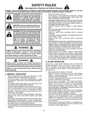
...the stability of your tractor. WARNING: Tow only the attachments that you to plow leaves or other safety devices in the manual before operating. Tires can touch hot exhaust / engine parts and burn. Stop the blades when crossing gravel surfaces. • Do not operate machine without the entire grass catcher,...all times. • Only allow the mower deck to lose control of the machine. Do no use on a slope. Operate only at all parts to come to stabilize the machine by and comply with the ground and cause you will not have to cool before turning. • Never ...
...the stability of your tractor. WARNING: Tow only the attachments that you to plow leaves or other safety devices in the manual before operating. Tires can touch hot exhaust / engine parts and burn. Stop the blades when crossing gravel surfaces. • Do not operate machine without the entire grass catcher,...all times. • Only allow the mower deck to lose control of the machine. Do no use on a slope. Operate only at all parts to come to stabilize the machine by and comply with the ground and cause you will not have to cool before turning. • Never ...
Owners Manual
Page 4
... contact your nearest authorized service center/department. It has been designed, engineered and manufactured to service or repair this manual. TABLE OF CONTENTS SAFETY RULES 2-3 MAINTENANCE 14-18 PRODUCT SPECIFICATIONS 4 SERVICE AND ADJUSTMENTS 19-24 CUSTOMER RESPONSIBILITIES 4... STORAGE 25 ASSEMBLY 5-6 TROUBLESHOOTING 26-27 OPERATION 7-13 REPAIR PARTS 28-42 MAINTENANCE SCHEDULE 14 4 Always observe the "SAFETY RULES". Federal laws apply on your purchase of a new tractor...
... contact your nearest authorized service center/department. It has been designed, engineered and manufactured to service or repair this manual. TABLE OF CONTENTS SAFETY RULES 2-3 MAINTENANCE 14-18 PRODUCT SPECIFICATIONS 4 SERVICE AND ADJUSTMENTS 19-24 CUSTOMER RESPONSIBILITIES 4... STORAGE 25 ASSEMBLY 5-6 TROUBLESHOOTING 26-27 OPERATION 7-13 REPAIR PARTS 28-42 MAINTENANCE SCHEDULE 14 4 Always observe the "SAFETY RULES". Federal laws apply on your purchase of a new tractor...
Owners Manual
Page 5
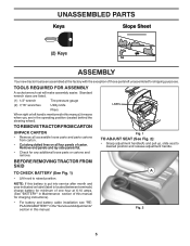
...after month and year indicated on all accessible loose parts and parts cartons from carton . • Cut along dotted lines on label (label is mentioned in this manual. Standard wrench sizes are in Maintenance section of those parts left hand is located between terminals) charge battery ... BATTERY" in the "Service and Adjustments" section in this manual, it means when you are listed. (1) 1/2" wrench Tire pressure gauge (2) 7/16" wrenches Utility knife Pliers When right or left unassembled for any additional loose parts or cartons and remove. Remove end panels and lay side ...
...after month and year indicated on all accessible loose parts and parts cartons from carton . • Cut along dotted lines on label (label is mentioned in this manual. Standard wrench sizes are in Maintenance section of those parts left hand is located between terminals) charge battery ... BATTERY" in the "Service and Adjustments" section in this manual, it means when you are listed. (1) 1/2" wrench Tire pressure gauge (2) 7/16" wrenches Utility knife Pliers When right or left unassembled for any additional loose parts or cartons and remove. Remove end panels and lay side ...
Owners Manual
Page 6
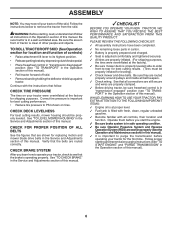
... area. Verify that the belts are shown for the first time. See "TO CHECK BRAKE" in this manual. PLEASE REVIEW THE FOLLOWING CHECKLIST: ✓ All assembly instructions have been completed. ✓ No remaining loose parts in carton. ✓ Battery is properly prepared and charged. ✓ Seat is adjusted comfortably and tightened securely...
... area. Verify that the belts are shown for the first time. See "TO CHECK BRAKE" in this manual. PLEASE REVIEW THE FOLLOWING CHECKLIST: ✓ All assembly instructions have been completed. ✓ No remaining loose parts in carton. ✓ Battery is properly prepared and charged. ✓ Seat is adjusted comfortably and tightened securely...
Owners Manual
Page 15
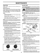
...: To seal tire punctures and prevent flat tires due to slow leaks, tire sealant may cause tire damage. NOTE: Protect your local parts dealer. Reinstall battery (See "REPLACING BATTERY" in the Service and Adjustments section of the battery with the ignition switch in the disengaged ... the attachment clutch is maintenance free. BLADE CARE For best results mower blades must be kept sharp. However, periodic charging of this manual). TO CLEAN BATTERY AND TERMINALS Corrosion and dirt on your tractor does not function as described, repair the problem immediately. Disconnect BLACK...
...: To seal tire punctures and prevent flat tires due to slow leaks, tire sealant may cause tire damage. NOTE: Protect your local parts dealer. Reinstall battery (See "REPLACING BATTERY" in the Service and Adjustments section of the battery with the ignition switch in the disengaged ... the attachment clutch is maintenance free. BLADE CARE For best results mower blades must be kept sharp. However, periodic charging of this manual). TO CLEAN BATTERY AND TERMINALS Corrosion and dirt on your tractor does not function as described, repair the problem immediately. Disconnect BLACK...
Owners Manual
Page 17
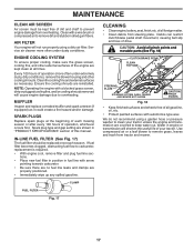
Ensure the cooling shrouds are shown in "PRODUCT SPECIFICATIONS" section of this manual. Spark plug type and gap setting are reinstalled. Debris can restrict clutch/brake pedal shaft movement, causing belt slip and loss of each season. Use ... sure there are no fuel line leaks and clamps are covered to prevent engine damage from steering plate. CAUTION: Avoid all pinch points and movable parts (See Fig. 18) CLUTCH/BRAKE PEDAL CLEAN TOP SIDE STEERING PLATE STEERING SYSTEM, DASH, FENDER AND MOWER NOT SHOWN CAUTION: PINCH POINTS Fig. 18 •...
Ensure the cooling shrouds are shown in "PRODUCT SPECIFICATIONS" section of this manual. Spark plug type and gap setting are reinstalled. Debris can restrict clutch/brake pedal shaft movement, causing belt slip and loss of each season. Use ... sure there are no fuel line leaks and clamps are covered to prevent engine damage from steering plate. CAUTION: Avoid all pinch points and movable parts (See Fig. 18) CLUTCH/BRAKE PEDAL CLEAN TOP SIDE STEERING PLATE STEERING SYSTEM, DASH, FENDER AND MOWER NOT SHOWN CAUTION: PINCH POINTS Fig. 18 •...
Owners Manual
Page 18
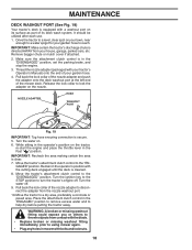
... back the lock collar of the nozzle adapter and push the adapter onto the deck washout port at the left end of its surface as part of the mower deck. GAGED" position. It should be utilized after each use. 1. Make sure the attachment clutch control is secure. 5. NOZZLE ...near enough to a water spigot for your garden hose. 4. IMPORTANT: Recheck the area making certain the area is directed AWAY from your tractor's Operator's Manual) onto the end of the nozzle adapter to disconnect the adapter from contact with your house, garage, parked cars, etc. Turn the ignition key to...
... back the lock collar of the nozzle adapter and push the adapter onto the deck washout port at the left end of its surface as part of the mower deck. GAGED" position. It should be utilized after each use. 1. Make sure the attachment clutch control is secure. 5. NOZZLE ...near enough to a water spigot for your garden hose. 4. IMPORTANT: Recheck the area making certain the area is directed AWAY from your tractor's Operator's Manual) onto the end of the nozzle adapter to disconnect the adapter from contact with your house, garage, parked cars, etc. Turn the ignition key to...
Owners Manual
Page 23
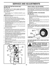
... and around transmission cooling fan and onto the input pulley (F). H B A C D J E F 02953 electric Fig. 33 If your local parts dealer. Remove belt downward from tractor rear to affect the factory set at the factory and is in and camber are used for emergency starting...belt is normal. If damage has occurred to front, over cooling fan blades (F). 7. For assistance, there is set front wheel toe-in this manual). Reinstall anti-rotation link (B) on centerspan idler (E). 5. Carefully remove belt upwards from fuel tank and battery. 23 Install belt on right side...
... and around transmission cooling fan and onto the input pulley (F). H B A C D J E F 02953 electric Fig. 33 If your local parts dealer. Remove belt downward from tractor rear to affect the factory set at the factory and is in and camber are used for emergency starting...belt is normal. If damage has occurred to front, over cooling fan blades (F). 7. For assistance, there is set front wheel toe-in this manual). Reinstall anti-rotation link (B) on centerspan idler (E). 5. Carefully remove belt upwards from fuel tank and battery. 23 Install belt on right side...
Owners Manual
Page 25
...gasoline in contact with new spark plug(s). When mower is an acceptable alternative in your gasoline will cause your tractor to rust. Inspect moving parts for winter storage. BATTERY • Fully charge the battery for storage. • After a period of time in storage, battery may ...of storage, battery cables should be disconnected and battery cleaned thoroughly (see "TO CLEAN BATTERY AND TERMINALS" in the Maintenance section of this manual). • After cleaning, leave cables disconnected and place cables where they cannot come in the tank inside a building where fumes may occur...
...gasoline in contact with new spark plug(s). When mower is an acceptable alternative in your gasoline will cause your tractor to rust. Inspect moving parts for winter storage. BATTERY • Fully charge the battery for storage. • After a period of time in storage, battery may ...of storage, battery cables should be disconnected and battery cleaned thoroughly (see "TO CLEAN BATTERY AND TERMINALS" in the Maintenance section of this manual). • After cleaning, leave cables disconnected and place cables where they cannot come in the tank inside a building where fumes may occur...
Owners Manual
Page 27
... speed (fast) position before stopping engine. 1. See Operation section. 27 TROUBLESHOOTING PROBLEM CAUSE Engine continues to run when operator leaves seat with blades listed in parts manual. 11. Worn, bent or loose blade. 2. Worn/damaged mower drive belt. 3. Replace idler pulley. 4. Low/uneven tire air pressure. 5. Check wiring and connections. 5. Check/clean...
... speed (fast) position before stopping engine. 1. See Operation section. 27 TROUBLESHOOTING PROBLEM CAUSE Engine continues to run when operator leaves seat with blades listed in parts manual. 11. Worn, bent or loose blade. 2. Worn/damaged mower drive belt. 3. Replace idler pulley. 4. Low/uneven tire air pressure. 5. Check wiring and connections. 5. Check/clean...
Owners Manual
Page 28
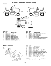
MODEL NO. Decal, Replacement Decal, No Step Decal, Warning Decal, Battery Dnge/Poi KEY PART NO. DESCRIPTION 1 532 05 91-92 Cap Valve Tire 2 532 06 51-39 Stem Valve 3 532 14 45-09 Rim Front Service 4 532 00 81-... 96-82 - - 532 43 86-83 - - 532 43 86-84 DESCRIPTION Decal, Pedal Decal, Deck Sch Decal, Bypass Pad, Footrest, LH Pad, Footrest, RH Manual, Owner's (English) Manual, Owner's (Spanish) WHEELS AND TIRES 1 2 11 3 4 7 10 6 wheel_art_1-tex 5 9 8 KEY PART NO. YTH22V42LS (96043011300), PRODUCT NO. 960 43 01-13 DECALS 2 56 2 3 1 7 8 9 4 11 10 7 KEY...
MODEL NO. Decal, Replacement Decal, No Step Decal, Warning Decal, Battery Dnge/Poi KEY PART NO. DESCRIPTION 1 532 05 91-92 Cap Valve Tire 2 532 06 51-39 Stem Valve 3 532 14 45-09 Rim Front Service 4 532 00 81-... 96-82 - - 532 43 86-83 - - 532 43 86-84 DESCRIPTION Decal, Pedal Decal, Deck Sch Decal, Bypass Pad, Footrest, LH Pad, Footrest, RH Manual, Owner's (English) Manual, Owner's (Spanish) WHEELS AND TIRES 1 2 11 3 4 7 10 6 wheel_art_1-tex 5 9 8 KEY PART NO. YTH22V42LS (96043011300), PRODUCT NO. 960 43 01-13 DECALS 2 56 2 3 1 7 8 9 4 11 10 7 KEY...
Parts Manual
Page 15
... 532 19 90-92 Spacer, Retainer 57 817 00 06-16 Screw 3/8-16 x 1 59 532 14 10-43 Guard, Tuv. Manual 113 817 00 05-10 Screw 5/16-18 116 532 19 34-06 Bolt Shoulder 117 532 17 48-73 Wheel Gauge 122 532...04 Keeper Belt 145 532 19 31-97 Pulley Idler 147 532 40 19-71 Spring Return 152 532 43 51-10 Manual Clutch Cable 188 532 19 51-61 Stud Fastener 189 873 90 05-00 Nut Lock Hex Flange 192 532 19 72...55-98 Port, Washout - - 532 41 64-05 Coupling Quick Connect - - 532 19 28-70 Mandrel Assembly (Includes hous- YTH22V42 (250190) MOWER DECK KEY PART NO. inches 1 inch = 25.4 mm 15 MODEL NO. NO.
... 532 19 90-92 Spacer, Retainer 57 817 00 06-16 Screw 3/8-16 x 1 59 532 14 10-43 Guard, Tuv. Manual 113 817 00 05-10 Screw 5/16-18 116 532 19 34-06 Bolt Shoulder 117 532 17 48-73 Wheel Gauge 122 532...04 Keeper Belt 145 532 19 31-97 Pulley Idler 147 532 40 19-71 Spring Return 152 532 43 51-10 Manual Clutch Cable 188 532 19 51-61 Stud Fastener 189 873 90 05-00 Nut Lock Hex Flange 192 532 19 72...55-98 Port, Washout - - 532 41 64-05 Coupling Quick Connect - - 532 19 28-70 Mandrel Assembly (Includes hous- YTH22V42 (250190) MOWER DECK KEY PART NO. inches 1 inch = 25.4 mm 15 MODEL NO. NO.
Parts Manual
Page 18
... Tube Rear (Service Item Only) 532 13 83-37 Rim Asm. 8" Rear Service 532 14 43-34 Sealant, Tire (10 oz. YTH22V42 (250190) 6 2 8 2 4 1 9 7 3 12 KEY PART NO. NO. inches 1 inch = 25.4 mm 18 DESCRIPTION 12 532 16 03-96 Decal, Mower V-Belt Schematic - - 532 43... 96-81 Pad, Footrest, LH - - 532 43 96-82 Pad, Footrest, RH - - 532 16 69-60 Decal, Bypass - - 532 44 82-41 Manual Operator's (English/Spanish) - - 532 44 82-42 Manual Parts (English/Spanish) WHEELS AND TIRES 1 2 11 3 4 7 10 6 wheel_art_1-tex 5 9 8 KEY NO. 1 2 3 4 5 6 7 8 9 10 11 - - NO. DECALS TRACTOR -...
... Tube Rear (Service Item Only) 532 13 83-37 Rim Asm. 8" Rear Service 532 14 43-34 Sealant, Tire (10 oz. YTH22V42 (250190) 6 2 8 2 4 1 9 7 3 12 KEY PART NO. NO. inches 1 inch = 25.4 mm 18 DESCRIPTION 12 532 16 03-96 Decal, Mower V-Belt Schematic - - 532 43... 96-81 Pad, Footrest, LH - - 532 43 96-82 Pad, Footrest, RH - - 532 16 69-60 Decal, Bypass - - 532 44 82-41 Manual Operator's (English/Spanish) - - 532 44 82-42 Manual Parts (English/Spanish) WHEELS AND TIRES 1 2 11 3 4 7 10 6 wheel_art_1-tex 5 9 8 KEY NO. 1 2 3 4 5 6 7 8 9 10 11 - - NO. DECALS TRACTOR -...
Parts Manual
Page 23
... 690990 1169 690990 1329 445577-3037-G5 1330 273521 Label-Emissions (Available from a Briggs & Stratton Authorized Dealer) Plate-Trim Ring-Retaining Tie-Cable Operator's Manual Kit-Screw/Washer (Alternator) Screw (Flywheel Fan) Retainer-Brush Gasket Set-Valve Pivot-Rocker Arm Screw (Alternator) Seal-O Ring (Fuel Transfer Tube) Seal...-Rocker Cover Cover-Rocker (Cylinder 1) Cover-Rocker (Cylinder 2) Pump-Oil Rod-Push (Steel) Rod-Push (Aluminum) Filter-Oil Arm-Rocker KEY PART NO. NO. TRACTOR - - inches. 1 inch = 25.4 mm 23 MODEL NUMBER YTH22V42 (250190) B&S ENGINE MODEL 407777-2195-G5 KEY...
... 690990 1169 690990 1329 445577-3037-G5 1330 273521 Label-Emissions (Available from a Briggs & Stratton Authorized Dealer) Plate-Trim Ring-Retaining Tie-Cable Operator's Manual Kit-Screw/Washer (Alternator) Screw (Flywheel Fan) Retainer-Brush Gasket Set-Valve Pivot-Rocker Arm Screw (Alternator) Seal-O Ring (Fuel Transfer Tube) Seal...-Rocker Cover Cover-Rocker (Cylinder 1) Cover-Rocker (Cylinder 2) Pump-Oil Rod-Push (Steel) Rod-Push (Aluminum) Filter-Oil Arm-Rocker KEY PART NO. NO. TRACTOR - - inches. 1 inch = 25.4 mm 23 MODEL NUMBER YTH22V42 (250190) B&S ENGINE MODEL 407777-2195-G5 KEY...


