

Owners Manual
Page 2
... wire where it . • Mow up and thrown by putting your tractor. WARNING: Tow only the attachments that are involved in the manual before turning. • Never leave a running machine unattended. WARNING Battery posts, terminals and related accessories contain lead and lead compounds, chemicals ... and proceed slowly straight down slopes. WARNING: Do not coast down slopes, not across. • Watch for traffic when operating near rotating parts or under the influence of alcohol or drugs. • Watch for holes, ruts, bumps, rocks, or other reproductive harm. SAFETY RULES ...
... wire where it . • Mow up and thrown by putting your tractor. WARNING: Tow only the attachments that are involved in the manual before turning. • Never leave a running machine unattended. WARNING Battery posts, terminals and related accessories contain lead and lead compounds, chemicals ... and proceed slowly straight down slopes. WARNING: Do not coast down slopes, not across. • Watch for traffic when operating near rotating parts or under the influence of alcohol or drugs. • Watch for holes, ruts, bumps, rocks, or other reproductive harm. SAFETY RULES ...

Owners Manual
Page 4
... Reverse: 0 - 2.9 Charging System: 15 AMPS @ 3600 RPM Battery: AMP/HR: 28 MIN. LBS. Please read and retain this owner's manual. If a spark arrester is used on federal lands. age" sections of the California Public Resources Code). WARNING: This tractor is equipped with an ... 4 MAINTENANCE 14-17 CUSTOMER RESPONSIBILITIES 4 SERVICE AND ADJUSTMENTS 18-23 ASSEMBLY 5-6 STORAGE 24 OPERATION 7-13 TROUBLESHOOTING 25-26 REPAIR PARTS 27-42 4 CUSTOMER RESPONSIBILITIES • Read and observe the safety rules. • Follow a regular schedule in effective working ...
... Reverse: 0 - 2.9 Charging System: 15 AMPS @ 3600 RPM Battery: AMP/HR: 28 MIN. LBS. Please read and retain this owner's manual. If a spark arrester is used on federal lands. age" sections of the California Public Resources Code). WARNING: This tractor is equipped with an ... 4 MAINTENANCE 14-17 CUSTOMER RESPONSIBILITIES 4 SERVICE AND ADJUSTMENTS 18-23 ASSEMBLY 5-6 STORAGE 24 OPERATION 7-13 TROUBLESHOOTING 25-26 REPAIR PARTS 27-42 4 CUSTOMER RESPONSIBILITIES • Read and observe the safety rules. • Follow a regular schedule in effective working ...
Owners Manual
Page 5
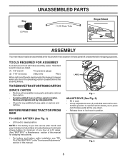
...carton. A Fig. 2 5 TO CHECK BATTERY (See Fig. 1) • Lift hood to press clutch/brake pedal all accessible loose parts and parts cartons from carton . • Cut along dotted lines on label (label is reached which allows you are in the operating position (seated...(See Fig. 2) • Sit in position. Key (2) Keys UNASSEMBLED PARTS (1) Oil Drain Tube Slope Sheet ASSEMBLY Your new tractor has been assembled at 6-10 amps. (See "BATTERY" in Maintenance section of this manual for charging instructions). • For battery and battery cable installation see "REPLACING...
...carton. A Fig. 2 5 TO CHECK BATTERY (See Fig. 1) • Lift hood to press clutch/brake pedal all accessible loose parts and parts cartons from carton . • Cut along dotted lines on label (label is reached which allows you are in the operating position (seated...(See Fig. 2) • Sit in position. Key (2) Keys UNASSEMBLED PARTS (1) Oil Drain Tube Slope Sheet ASSEMBLY Your new tractor has been assembled at 6-10 amps. (See "BATTERY" in Maintenance section of this manual for charging instructions). • For battery and battery cable installation see "REPLACING...

Owners Manual
Page 6
...Check mower and drive belts. PLEASE REVIEW THE FOLLOWING CHECKLIST: ✓ All assembly instructions have been completed. ✓ No remaining loose parts in the Operation section of controls) • Raise attachment lift lever to its highest position. • Release parking brake by depressing ...WARNING: Before starting and transmission purging instructions (See "TO START ENGINE" and "PURGE TRANSMISSION" in the Operation section of this manual. ✓CHECKLIST BEFORE YOU OPERATE YOUR NEW TRACTOR, WE WISH TO ASSURE THAT YOU RECEIVE THE BEST PERFORMANCE AND SATISFACTION FROM...
...Check mower and drive belts. PLEASE REVIEW THE FOLLOWING CHECKLIST: ✓ All assembly instructions have been completed. ✓ No remaining loose parts in the Operation section of controls) • Raise attachment lift lever to its highest position. • Release parking brake by depressing ...WARNING: Before starting and transmission purging instructions (See "TO START ENGINE" and "PURGE TRANSMISSION" in the Operation section of this manual. ✓CHECKLIST BEFORE YOU OPERATE YOUR NEW TRACTOR, WE WISH TO ASSURE THAT YOU RECEIVE THE BEST PERFORMANCE AND SATISFACTION FROM...

Owners Manual
Page 15
...charging of the battery with grease or petroleum jelly. • Reinstall battery (See "REPLACING BATTERY" in the SERVICE AND ADJUSTMENTS section of this manual). NOTE: The original equipment battery on your tractor does not function as described, repair the problem immediately. ROS "ON" POSITION 02828 ENGINE "... blade with the ignition switch in the Service and Adjustments section of your tractor is in the seat. NOTE: Protect your local parts dealer. IMPORTANT: TO ENSURE PROPER ASSEMBLY, CENTER HOLE IN BLADE MUST ALIGN WITH STAR ON MANDREL ASSEMBLY. • Install and tighten...
...charging of the battery with grease or petroleum jelly. • Reinstall battery (See "REPLACING BATTERY" in the SERVICE AND ADJUSTMENTS section of this manual). NOTE: The original equipment battery on your tractor does not function as described, repair the problem immediately. ROS "ON" POSITION 02828 ENGINE "... blade with the ignition switch in the Service and Adjustments section of your tractor is in the seat. NOTE: Protect your local parts dealer. IMPORTANT: TO ENSURE PROPER ASSEMBLY, CENTER HOLE IN BLADE MUST ALIGN WITH STAR ON MANDREL ASSEMBLY. • Install and tighten...
Owners Manual
Page 17
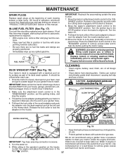
...water and to keep water out. CLEANING • Clean engine, battery, seat, finish, etc. CAUTION: Avoid all pinch points and movable parts (See Fig. 19) CLUTCH/BRAKE PEDAL CLEAN TOP SIDE STEERING PLATE NOZZLE ADAPTER HOSE WASHOUT PORT CAUTION: PINCH POINTS STEERING SYSTEM, DASH, .... mission are properly positioned. • Immediately wipe up any holes in "PRODUCT SPECIFICATIONS" section of your tractor's Operator's Manual) onto the end of this manual. Remove bagger chute or mulch cover if attached. 2. While sitting in fuel line with the cutting deck engaged until the...
...water and to keep water out. CLEANING • Clean engine, battery, seat, finish, etc. CAUTION: Avoid all pinch points and movable parts (See Fig. 19) CLUTCH/BRAKE PEDAL CLEAN TOP SIDE STEERING PLATE NOZZLE ADAPTER HOSE WASHOUT PORT CAUTION: PINCH POINTS STEERING SYSTEM, DASH, .... mission are properly positioned. • Immediately wipe up any holes in "PRODUCT SPECIFICATIONS" section of your tractor's Operator's Manual) onto the end of this manual. Remove bagger chute or mulch cover if attached. 2. While sitting in fuel line with the cutting deck engaged until the...

Owners Manual
Page 22
...from fuel tank and battery. 22 TERMINAL COVER POSITIVE (RED) CABLE Fig. 34 NEGATIVE (BLACK) CABLE Tighten securely • Close hood. If your local parts dealer. THE OTHER VEHICLE MUST ALSO BE A 12 VOLT SYSTEM. TO ATTACH JUMPER CABLES - • Connect one end of the RED cable to the ... and washers to good chassis ground, away from tractor. • Install new battery with terminals in and camber are used for emergency starting, follow this manual). WASHERS RETAINING RING AXLE COVER SQUARE KEY (REAR WHEEL ONLY) Fig. 32 TO START ENGINE WITH A WEAK BATTERY (See Fig. 33) WEAK OR...
...from fuel tank and battery. 22 TERMINAL COVER POSITIVE (RED) CABLE Fig. 34 NEGATIVE (BLACK) CABLE Tighten securely • Close hood. If your local parts dealer. THE OTHER VEHICLE MUST ALSO BE A 12 VOLT SYSTEM. TO ATTACH JUMPER CABLES - • Connect one end of the RED cable to the ... and washers to good chassis ground, away from tractor. • Install new battery with terminals in and camber are used for emergency starting, follow this manual). WASHERS RETAINING RING AXLE COVER SQUARE KEY (REAR WHEEL ONLY) Fig. 32 TO START ENGINE WITH A WEAK BATTERY (See Fig. 33) WEAK OR...

Owners Manual
Page 23
...FUSE Replace with 20 amp automotive-type plug-in the Repair Parts section. TO ADJUST CHOKE CONTROL The choke control has been preset at the factory and adjustment should not be necessary. If adjustment is necessary, see engne manual. TO REMOVE HOOD AND GRILL ASSEMBLY (See Fig. 35) ...• Raise hood. • Unsnap headlight wire connector. • Stand in front of this manual. If adjustment is necessary, see engine manual. HOOD HEADLIGHT WIRE CONNECTOR 07002 Fig. 35 23 TO ADJUST CARBURETOR Your carburetor is located behind the dash. See electrical wiring ...
...FUSE Replace with 20 amp automotive-type plug-in the Repair Parts section. TO ADJUST CHOKE CONTROL The choke control has been preset at the factory and adjustment should not be necessary. If adjustment is necessary, see engne manual. TO REMOVE HOOD AND GRILL ASSEMBLY (See Fig. 35) ...• Raise hood. • Unsnap headlight wire connector. • Stand in front of this manual. If adjustment is necessary, see engine manual. HOOD HEADLIGHT WIRE CONNECTOR 07002 Fig. 35 23 TO ADJUST CARBURETOR Your carburetor is located behind the dash. See electrical wiring ...

Owners Manual
Page 24
... lines and carburetor are securely fastened. placement instructions in the Service and Adjustments section of this manual). • Lubricate as shown in contact with new spark plug(s). Inspect moving parts for winter storage. ACIDIC GAS CAN DAMAGE THE FUEL SYSTEM OF AN ENGINE WHILE IN STORAGE.... cannot come in the Maintenance section of time, clean it thoroughly, remove all dirt, grease, leaves, etc. nance section of this manual). ALSO, EXPERIENCE INDICATES THAT ALCOHOL BLENDED FUELS (CALLED GASOHOL OR USING ETHANOL OR METHANOL) CAN ATTRACT MOISTURE WHICH LEADS TO SEPARATION AND...
... lines and carburetor are securely fastened. placement instructions in the Service and Adjustments section of this manual). • Lubricate as shown in contact with new spark plug(s). Inspect moving parts for winter storage. ACIDIC GAS CAN DAMAGE THE FUEL SYSTEM OF AN ENGINE WHILE IN STORAGE.... cannot come in the Maintenance section of time, clean it thoroughly, remove all dirt, grease, leaves, etc. nance section of this manual). ALSO, EXPERIENCE INDICATES THAT ALCOHOL BLENDED FUELS (CALLED GASOHOL OR USING ETHANOL OR METHANOL) CAN ATTRACT MOISTURE WHICH LEADS TO SEPARATION AND...

Owners Manual
Page 26
... half and full speed (fast) position before stopping engine. 1. TROUBLESHOOTING POINTS PROBLEM CAUSE Engine continues to run when operator leaves seat with blades listed in parts manual. 11. CORRECTION 1. Worn, bent or loose blade. 2. Buildup of grass, leaves, trash under mower. 4. Worn/damaged mower drive belt. 3. Check tires for proper air pressure...
... half and full speed (fast) position before stopping engine. 1. TROUBLESHOOTING POINTS PROBLEM CAUSE Engine continues to run when operator leaves seat with blades listed in parts manual. 11. CORRECTION 1. Worn, bent or loose blade. 2. Buildup of grass, leaves, trash under mower. 4. Worn/damaged mower drive belt. 3. Check tires for proper air pressure...

Owners Manual
Page 39
... - - 532 43 18-23 Arm Brake Mower Linkage Brake Handle, Clutch Cable V-Belt Bolt Clutch Asm. RH Keeper Belt Pulley Idler Spring Return Cable Clutch Manual w/Spr. Keeper Belt Eng. Baffle Center Front Baffle Front RH Washer 13/32 x 1 x 1/2 11 Ga. LH Keeper Belt Eng. NO. TRACTOR - - DESCRIPTION 1 532 ... x 1 59 532 14 10-43 Guard, Tuv Idler (94) 60 532 19 94-71 Arm Brake Mower LH KEY PART NO. MODEL NUMBER YTH21K46 (96045002901), PRODUCT NO. 960 45 00-29 MOWER DECK KEY PART NO. NO. Cable Screw 5/16-18 Bolt, Shoulder Wheel, Gauge Washer 13/32 x 1-1/4 x 12 Ga. inches 1 inch =...
... - - 532 43 18-23 Arm Brake Mower Linkage Brake Handle, Clutch Cable V-Belt Bolt Clutch Asm. RH Keeper Belt Pulley Idler Spring Return Cable Clutch Manual w/Spr. Keeper Belt Eng. Baffle Center Front Baffle Front RH Washer 13/32 x 1 x 1/2 11 Ga. LH Keeper Belt Eng. NO. TRACTOR - - DESCRIPTION 1 532 ... x 1 59 532 14 10-43 Guard, Tuv Idler (94) 60 532 19 94-71 Arm Brake Mower LH KEY PART NO. MODEL NUMBER YTH21K46 (96045002901), PRODUCT NO. 960 45 00-29 MOWER DECK KEY PART NO. NO. Cable Screw 5/16-18 Bolt, Shoulder Wheel, Gauge Washer 13/32 x 1-1/4 x 12 Ga. inches 1 inch =...

Owners Manual
Page 42
...Schematic Decal, Bypass Pad, Footrest, LH Pad, Footrest, RH Manual, Owner's (English) Manual, Owner's (Spanish) KEY PART NO. Tube) NOTE: All component dimensions given in U.S. ...Decal, Replacement Decal, Label Emiss. Decal, Fender WHEELS AND TIRES 1 2 11 3 4 7 10 6 5 9 8 wheel_art_1-tex KEY NO. 9 10 12 - - - - - - inches 1 inch = 25.4 mm 42 MODEL NUMBER YTH21K46 (96045002901), PRODUCT NO. 960 45 00-29 DECALS 47 2 56 2 8 3 1 9 10 KEY NO. 1 2 3 4 5 6 7 8 12 PART...
...Schematic Decal, Bypass Pad, Footrest, LH Pad, Footrest, RH Manual, Owner's (English) Manual, Owner's (Spanish) KEY PART NO. Tube) NOTE: All component dimensions given in U.S. ...Decal, Replacement Decal, Label Emiss. Decal, Fender WHEELS AND TIRES 1 2 11 3 4 7 10 6 5 9 8 wheel_art_1-tex KEY NO. 9 10 12 - - - - - - inches 1 inch = 25.4 mm 42 MODEL NUMBER YTH21K46 (96045002901), PRODUCT NO. 960 45 00-29 DECALS 47 2 56 2 8 3 1 9 10 KEY NO. 1 2 3 4 5 6 7 8 12 PART...

Parts List
Page 14
... Washer 13/32 x 13/16 x 12 Ga. NO. NO. Keeper Belt Eng. inches 1 inch = 25.4 mm 39 MODEL NUMBER YTH21K46 (96045002601), PRODUCT NO. 960 45 00-26 MOWER DECK KEY PART NO. LH Keeper Belt Eng. pulley/nut/washer and blade bolt/washers not included) Replacement Mower, Complete NOTE: All component...16 x 1 59 532 14 10-43 Guard, Tuv Idler (94) 60 532 19 94-71 Arm Brake Mower LH KEY PART NO. RH Keeper Belt Pulley Idler Spring Return Cable Clutch Manual w/Spr. Bolt 3/8-16 unc x 2-1/4 Gr. 5 Screw Washout Port Quick Connect Coupling Mandrel Assembly (Includes housing, shaft assembly,...
... Washer 13/32 x 13/16 x 12 Ga. NO. NO. Keeper Belt Eng. inches 1 inch = 25.4 mm 39 MODEL NUMBER YTH21K46 (96045002601), PRODUCT NO. 960 45 00-26 MOWER DECK KEY PART NO. LH Keeper Belt Eng. pulley/nut/washer and blade bolt/washers not included) Replacement Mower, Complete NOTE: All component...16 x 1 59 532 14 10-43 Guard, Tuv Idler (94) 60 532 19 94-71 Arm Brake Mower LH KEY PART NO. RH Keeper Belt Pulley Idler Spring Return Cable Clutch Manual w/Spr. Bolt 3/8-16 unc x 2-1/4 Gr. 5 Screw Washout Port Quick Connect Coupling Mandrel Assembly (Includes housing, shaft assembly,...

Parts List
Page 17
...) NOTE: All component dimensions given in U.S. PART NO. DESCRIPTION 532 05 91-92 532 06 51-39 532 13 83-36...AND TIRES 1 2 11 3 4 7 10 5 9 6 8 wheel_art_1-tex KEY NO. 9 12 - - - - - - MODEL NUMBER YTH21K46 (96045002601), PRODUCT NO. 960 45 00-26 DECALS 2 56 2 8 9 3 1 4 12 KEY NO. 1 2 3 4 5 6 8 PART NO. TRACTOR - - DESCRIPTION 532 41 91-38 532 42 91-96 532 43 95-66 532 17 05-63... Dnge/Poi Decal, Mower V-Belt Schematic Decal, Bypass Pad, Footrest, LH Pad, Footrest, RH Manual, Owner's (English) Manual, Owner's (Spanish) KEY NO. 1 2 3 4 5 6 7 8 9 10 11 - -
...) NOTE: All component dimensions given in U.S. PART NO. DESCRIPTION 532 05 91-92 532 06 51-39 532 13 83-36...AND TIRES 1 2 11 3 4 7 10 5 9 6 8 wheel_art_1-tex KEY NO. 9 12 - - - - - - MODEL NUMBER YTH21K46 (96045002601), PRODUCT NO. 960 45 00-26 DECALS 2 56 2 8 9 3 1 4 12 KEY NO. 1 2 3 4 5 6 8 PART NO. TRACTOR - - DESCRIPTION 532 41 91-38 532 42 91-96 532 43 95-66 532 17 05-63... Dnge/Poi Decal, Mower V-Belt Schematic Decal, Bypass Pad, Footrest, LH Pad, Footrest, RH Manual, Owner's (English) Manual, Owner's (Spanish) KEY NO. 1 2 3 4 5 6 7 8 9 10 11 - -


