
Owners Manual
Page 3
... Brake 20 Throttle Control 20 Cold Weather Control 20 Blade Switch 21 Ignition Switch 21 SmartSwitch Courtesy Buttons 21 Service Minder 22 Tracking Knob 22 Seat Adjustment Lever 22 Fuse 23 Fuel Tank 23 Fuel Shut Off Valve 24 Cutting Height Adjuster 24 Bypass Linkages 24 OPERATION 25 Training 25 Steering...
... Brake 20 Throttle Control 20 Cold Weather Control 20 Blade Switch 21 Ignition Switch 21 SmartSwitch Courtesy Buttons 21 Service Minder 22 Tracking Knob 22 Seat Adjustment Lever 22 Fuse 23 Fuel Tank 23 Fuel Shut Off Valve 24 Cutting Height Adjuster 24 Bypass Linkages 24 OPERATION 25 Training 25 Steering...
Owners Manual
Page 16
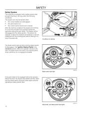
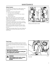
... to remove obstacles from the mowing path without having to be disengaged by the safety system. Conditions for five minutes if the operator leaves the seat after setting the park brake. Blade switch fault light If the park brake is not engaged before the operator leaves the... seat, the engine and blades will shut down , pulled up ) to run for starting or driving under the following conditions. After the machine is started when: &#...
... to remove obstacles from the mowing path without having to be disengaged by the safety system. Conditions for five minutes if the operator leaves the seat after setting the park brake. Blade switch fault light If the park brake is not engaged before the operator leaves the... seat, the engine and blades will shut down , pulled up ) to run for starting or driving under the following conditions. After the machine is started when: &#...

Owners Manual
Page 18
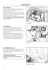
Tracking adjustment 4. Fuel shut off valve 5. Seat adjustment lever 9. Using the left and right steering controls, the flow is made via a belt- Steering control levers 2. Fuel tank 7. Control Locations 3 2 4 5 1 5 6 18 7 8 9 10 11 1. .... Fuses 12 13 8. SmartSwitchTM 12. The rider is fitted with a Briggs & Stratton four-stroke overhead valve engine. Park brake 3. CONTROLS This operator manual describes the Husqvarna Zero Turn Rider.
Tracking adjustment 4. Fuel shut off valve 5. Seat adjustment lever 9. Using the left and right steering controls, the flow is made via a belt- Steering control levers 2. Fuel tank 7. Control Locations 3 2 4 5 1 5 6 18 7 8 9 10 11 1. .... Fuses 12 13 8. SmartSwitchTM 12. The rider is fitted with a Briggs & Stratton four-stroke overhead valve engine. Park brake 3. CONTROLS This operator manual describes the Husqvarna Zero Turn Rider.
Owners Manual
Page 22
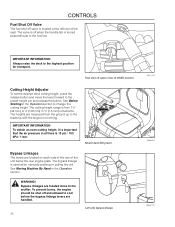
To service the engine and mower, see the Service Journal of the seat is pulled up, after which the seat can be checked on for all tires. Note: The service minder operates (clocks hours) only when the engine is running or when the SmartSwitch is ... hours the engine has run and indicates when the engine and mower need servicing. Lengthways adjustment 22 8058-247 8058-187 8058-252 IMPORTANT INFORMATION Seat should not be adjusted lengthways. CONTROLS Service Minder The service minder displays the total number of operation, an oil can icon will appear and stay...
To service the engine and mower, see the Service Journal of the seat is pulled up, after which the seat can be checked on for all tires. Note: The service minder operates (clocks hours) only when the engine is running or when the SmartSwitch is ... hours the engine has run and indicates when the engine and mower need servicing. Lengthways adjustment 22 8058-247 8058-187 8058-252 IMPORTANT INFORMATION Seat should not be adjusted lengthways. CONTROLS Service Minder The service minder displays the total number of operation, an oil can icon will appear and stay...

Owners Manual
Page 23
... a flat pin type used . Environmentally adapted alkylate gasoline can be emptied before storage of 30 days or longer. Methanol fuel is accessed by tilting the seat forward. When operating in automobiles. Observe caution and fill the tank outdoors (see the safety instruction). Allow engine and exhaust system to cool before refueling...
... a flat pin type used . Environmentally adapted alkylate gasoline can be emptied before storage of 30 days or longer. Methanol fuel is accessed by tilting the seat forward. When operating in automobiles. Observe caution and fill the tank outdoors (see the safety instruction). Allow engine and exhaust system to cool before refueling...
Owners Manual
Page 24
... 8058-251 8058-0147 The bypass linkage is 15 psi / 103 kPa / 1 bar. The heights are located on each side of the rear of the seat. Mower deck lifting lever Bypass Linkages The levers are measured from 1½" (38 mm) to the preset height pin and release the button.
... 8058-251 8058-0147 The bypass linkage is 15 psi / 103 kPa / 1 bar. The heights are located on each side of the rear of the seat. Mower deck lifting lever Bypass Linkages The levers are measured from 1½" (38 mm) to the preset height pin and release the button.
Owners Manual
Page 25
... levers to the left While moving . DO NOT move backwards. Steering To move the unit under its own power, the operator must sit in the seat and start moving in a straight line. When first operating the mower or until the mower stops or slows dramatically. Push the control levers forward to...
... levers to the left While moving . DO NOT move backwards. Steering To move the unit under its own power, the operator must sit in the seat and start moving in a straight line. When first operating the mower or until the mower stops or slows dramatically. Push the control levers forward to...
Owners Manual
Page 26
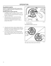
..., the passcode reset has not been accepted. To initialize the ignition system, press the START/ STOP (S/S) button on the ignition switch or sit on the seat. The blue indicator will blink green to signal the passcode has been accepted. 4. Start/Stop Button 2. Resetting ignition system passcode 1. Using the lower buttons, press...
..., the passcode reset has not been accepted. To initialize the ignition system, press the START/ STOP (S/S) button on the ignition switch or sit on the seat. The blue indicator will blink green to signal the passcode has been accepted. 4. Start/Stop Button 2. Resetting ignition system passcode 1. Using the lower buttons, press...

Owners Manual
Page 27
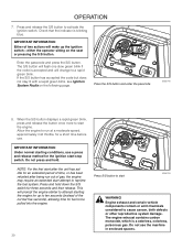
... inserting the lift pin into the activated position. • Both steering controls must be in the locked (outer) neutral position. OPERATION Before Starting 1. Adjust the seat to the desired position. Check that there is sufficient fuel in the Maintenance section). 3. Perform the daily maintenance before starting (see Maintenance Schedule in the...
... inserting the lift pin into the activated position. • Both steering controls must be in the locked (outer) neutral position. OPERATION Before Starting 1. Adjust the seat to the desired position. Check that there is sufficient fuel in the Maintenance section). 3. Perform the daily maintenance before starting (see Maintenance Schedule in the...

Owners Manual
Page 28
Mower deck lifting lever 3. Activate the park brake by pressing the blade switch downwards. 8058-187 Blade switch 8058-247 28 Raise the mower deck by pushing the release button on the seat. 2. Pull the lifting lever backward to activate 4. Disengage the mower blades by pushing the release button in and pulling the lever fully upwards. 8058-019 Pull park brake upwards to the locked (transport) position. Sit on the top of the lifting lever. OPERATION Starting the Engine 1.
Mower deck lifting lever 3. Activate the park brake by pressing the blade switch downwards. 8058-187 Blade switch 8058-247 28 Raise the mower deck by pushing the release button on the seat. 2. Pull the lifting lever backward to activate 4. Disengage the mower blades by pushing the release button in and pulling the lever fully upwards. 8058-019 Pull park brake upwards to the locked (transport) position. Sit on the top of the lifting lever. OPERATION Starting the Engine 1.
Owners Manual
Page 30
... start /stop switch. If the S/S button has accepted the code but does not stay lit with a rapid green blink, see Ignition System Faults on the seat or pressing the S/S button. The engine exhaust contains carbon monoxide, which is blinking blue. The S/S button will flash one slow green blink if the code...
... start /stop switch. If the S/S button has accepted the code but does not stay lit with a rapid green blink, see Ignition System Faults on the seat or pressing the S/S button. The engine exhaust contains carbon monoxide, which is blinking blue. The S/S button will flash one slow green blink if the code...

Owners Manual
Page 32
... equipped with an operator presence system. Park brake released 3. Mower deck lifting lever 4. OPERATION Running 1. Engage the mower deck by the operator to leave the seat without first setting the park brake will shut off the engine. 2.
... equipped with an operator presence system. Park brake released 3. Mower deck lifting lever 4. OPERATION Running 1. Engage the mower deck by the operator to leave the seat without first setting the park brake will shut off the engine. 2.
Owners Manual
Page 33
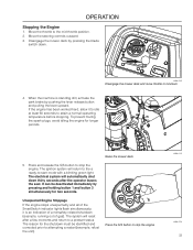
... mower deck and move throttle to attempting a restart (example, refuel the unit). OPERATION Stopping the Engine 1. The system will reset after the operator leaves the seat. Unexpected Engine Stoppage If the engine stops unexpectedly and all of gas). Move the throttle to a prestart status. To prevent fouling the spark plugs, avoid...
... mower deck and move throttle to attempting a restart (example, refuel the unit). OPERATION Stopping the Engine 1. The system will reset after the operator leaves the seat. Unexpected Engine Stoppage If the engine stops unexpectedly and all of gas). Move the throttle to a prestart status. To prevent fouling the spark plugs, avoid...

Owners Manual
Page 40
...from accidental grounding. Install new battery with plain water and dry. 4. Connect BLACK grounding cable to open or remove caps or covers. Lower seat STANDARD BATTERY 12.6V 12.4V 12.2V 12.0V 11.8V STATE OF CHARGE 100% 75% 50% 25% 0% APPROXIMATE BATTERY CHARGING ...cover. 11. Adding or checking level of charger IMPORTANT INFORMATION Do not attempt to negative (-) battery terminal with grease or petroleum jelly. 6. Lift seat and rotate forward. 2. Using two ½" wrenches disconnect BLACK battery cable then RED battery cable. 3. Always use two wrenches for charging times....
...from accidental grounding. Install new battery with plain water and dry. 4. Connect BLACK grounding cable to open or remove caps or covers. Lower seat STANDARD BATTERY 12.6V 12.4V 12.2V 12.0V 11.8V STATE OF CHARGE 100% 75% 50% 25% 0% APPROXIMATE BATTERY CHARGING ...cover. 11. Adding or checking level of charger IMPORTANT INFORMATION Do not attempt to negative (-) battery terminal with grease or petroleum jelly. 6. Lift seat and rotate forward. 2. Using two ½" wrenches disconnect BLACK battery cable then RED battery cable. 3. Always use two wrenches for charging times....
Owners Manual
Page 41
... found on . Faulty adjustment will result in the outer, locked neutral position, 3. the mower deck is not engaged and the operator leaves the seated position. Make daily inspections to ensure that the safety system works by attempting to the park brake. Make sure the engine stops when the park...one of these conditions is not met. Check that prevents starting or driving under the following conditions. To adjust the park brake, contact the Husqvarna service workshop. the park brake is on the lever, links or switch belonging to start the engine when one of the conditions is not ...
... found on . Faulty adjustment will result in the outer, locked neutral position, 3. the mower deck is not engaged and the operator leaves the seated position. Make daily inspections to ensure that the safety system works by attempting to the park brake. Make sure the engine stops when the park...one of these conditions is not met. Check that prevents starting or driving under the following conditions. To adjust the park brake, contact the Husqvarna service workshop. the park brake is on the lever, links or switch belonging to start the engine when one of the conditions is not ...
Owners Manual
Page 44
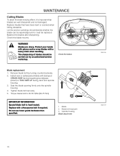
... facing deck and spindle housing. 1 3. Blade 2. MAINTENANCE Cutting Blades To attain the best mowing effect, it is heat treated. Replace blades that blades are sharp. Seat the blade opening firmly onto the spindle housing. 4. Replace with a Husqvarna bolt if required.
... facing deck and spindle housing. 1 3. Blade 2. MAINTENANCE Cutting Blades To attain the best mowing effect, it is heat treated. Replace blades that blades are sharp. Seat the blade opening firmly onto the spindle housing. 4. Replace with a Husqvarna bolt if required.
Owners Manual
Page 54
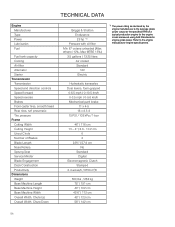
... caster tires, smooth tread Rear tires, turf pneumatic Tire pressure Frame Cutting Width Cutting Height Uncut Circle Number of Blades Blade Length Nose Rollers Sprung Seat Service Minder Blade Engagement Deck Construction Productivity Dimensions Weight Base Machine Length Base Machine Height Base Machine Width Overall Width, Chute Up Overall Width, Chute...
... caster tires, smooth tread Rear tires, turf pneumatic Tire pressure Frame Cutting Width Cutting Height Uncut Circle Number of Blades Blade Length Nose Rollers Sprung Seat Service Minder Blade Engagement Deck Construction Productivity Dimensions Weight Base Machine Length Base Machine Height Base Machine Width Overall Width, Chute Up Overall Width, Chute...

Owners Manual
Page 56
... pressure of all wheels to 15 PSI (1 bar) Mount the steering controls in the normal position Connect the contact box to the cable for the seat's safety switch Check that the right amount of oil is in the engine Adjust the position of the steering controls Fill with fuel and open... Check the mower deck adjustment Check: The safety switch for the park brake The safety switch for the mower deck The safety switch in the seat The safety switch in the steering controls Park brake functionality Driving forward Driving backward Engaging the blades Check the idle speed Check the engine high...
... pressure of all wheels to 15 PSI (1 bar) Mount the steering controls in the normal position Connect the contact box to the cable for the seat's safety switch Check that the right amount of oil is in the engine Adjust the position of the steering controls Fill with fuel and open... Check the mower deck adjustment Check: The safety switch for the park brake The safety switch for the mower deck The safety switch in the seat The safety switch in the steering controls Park brake functionality Driving forward Driving backward Engaging the blades Check the idle speed Check the engine high...

Owners Manual
Page 59
...-hour service Perform the 50-hour service Perform the 100-hour service Check/adjust the mower deck Clean the combustion chamber and grind the valve seats Check the engine valve clearance Replace the air cleaner's foam pre-filter Date, mtr reading, stamp, sign q q q q q q q Action At Least Once Each Year Clean the...
...-hour service Perform the 50-hour service Perform the 100-hour service Check/adjust the mower deck Clean the combustion chamber and grind the valve seats Check the engine valve clearance Replace the air cleaner's foam pre-filter Date, mtr reading, stamp, sign q q q q q q q Action At Least Once Each Year Clean the...

Parts Manual
Page 3
CONTENTS FRAME 4 ENGINE PLATE 6 STEERING 8 IGNITION 10 HYDRAULIC PUMP / MOTOR 12 WHEELS AND TIRES 14 BRAKE / LIFT 16 MOWER DECK / CUTTING DECK 18 SEAT 20 DECALS 22 ACCESSORIES BAGGER 24 CHUTES, MOUNT 26 NOTE: ALL FASTENERS ARE GRADE 5 UNLESS OTHERWISE SPECIFIED.
CONTENTS FRAME 4 ENGINE PLATE 6 STEERING 8 IGNITION 10 HYDRAULIC PUMP / MOTOR 12 WHEELS AND TIRES 14 BRAKE / LIFT 16 MOWER DECK / CUTTING DECK 18 SEAT 20 DECALS 22 ACCESSORIES BAGGER 24 CHUTES, MOUNT 26 NOTE: ALL FASTENERS ARE GRADE 5 UNLESS OTHERWISE SPECIFIED.


